robotics project

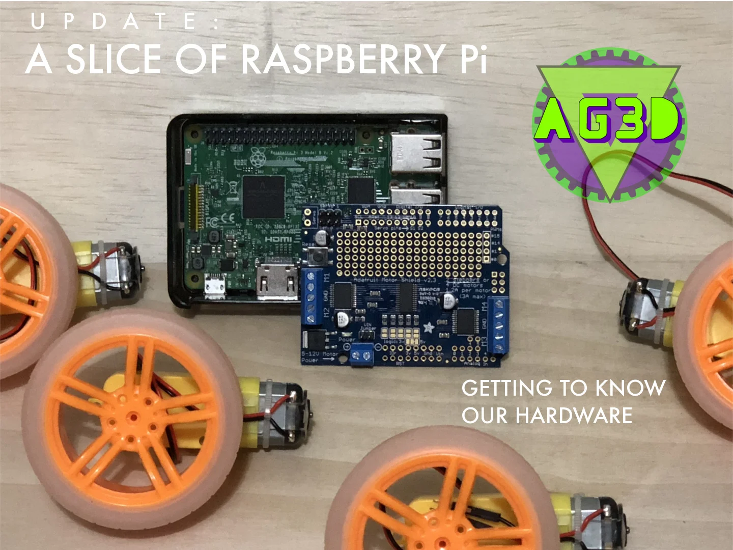
A Slice of Raspberry Pi: Getting to know our hardware

ENGINEERING UPDATE

With quite a few robotics and engineering projects ahead, it's important to get familiar with some of our hardware. The better we know our hardware, the more we can leverage it to solve our problems, and troubleshoot any problems we might have along the way. In this update I want to go over some of the hardware we'll be using and give a quick overview for both those who are new to robotics or just want to learn more about our upcoming 3D printing engineering projects.

If you missed our last post, this year we are focusing on engineering projects! See our last post to learn what 3D printing and engineering projects we have planned.


HARDWARE

RASPBERRY PI

HardwareRaspPi.jpg

The core of our projects are centered around the RaspberryPi, which is an affordable and completely customizable computer that in this case, is no larger than a deck of playing cards. The RaspberryPi was created by the London-based charity the RaspberryPi Foundation whose goal is to "put the power of digital making into the hands of people all over the world, so they are capable of understanding and shaping our increasingly digital world, able to solve the problems that matter to them, and equipped for the jobs of the future.". There are plenty of free software, tutorials, communities, and apps you can use to learn and use your RaspberryPi to it's full potential.

We will be using the Raspberry Pi 3 Model B, as it's the latest model on the market. It has the ability to connect to Wifi, which will make operating and developing on the fly much easier.

Here is a list of it's features:

  • 1.2GHz 64-bit quad-core ARMv8 CPU
  • 802.11n Wireless LAN
  • Bluetooth 4.1
  • Bluetooth Low Energy (BLE)
  • 4 USB ports
  • 40 GPIO pins
  • Full HDMI port
  • Ethernet port
  • Combined 3.5mm audio jack and composite video
  • Camera interface (CSI)
  • Display interface (DSI)
  • Micro SD card slot
  • VideoCore IV 3D graphics core
  • Switched Micro USB power source (now supports up to 2.5 Amps)

All of that packed into a tiny computer you can purchase for under $50. 

If you've been around the engineering block and know all about these tiny miracle computers, you might ask "Why RaspberryPi"? The short answer is support and simplicity. The Raspberry Pi community is large so there are lots of resources out there if things get confusing. There are also a lot of sources out there for programming in Python. But most of all, it's the availability of custom hardware that we can choose and program to solve the problems we're looking to solve. I also have found the amazing Adafruit shop, that not only supplies custom hardware for electronics projects like the Raspberry Pi, but it has tutorials and educational kits so that you can get started learning as soon as you get your parts. A big thank you to Lady Ada and the Adafruit team for their high quality products. I am not sponsored by them, but I definitely believe they have high quality products and it's why I chose them for most of our project hardware.

BREADBOARDS

CREDIT: ARDUINO ÖRNEKLERİ

CREDIT: ARDUINO ÖRNEKLERİ

In order to make sure our projects work, we'll need to test them along the way. In order to do that we'll need to use something called a breadboard. As the legend goes, they are called 'breadboards' because back in the day an engineer needed something to create an electrical circuit for a project. Looking around they found the closest thing to them, the wooden breadboard. Wood, as you might remember from science class, is NOT a good electrical conductor. So it was a decent thing to use since it was readily available (not to mention, cheap). It's not the safest thing, but they get an A+ for ingenuity!

Today, these boards are made from plastic like ABS, the same material Legos are made of. They have little metal clips in each hole that allow for electrical components to be mounted and tested WITHOUT needing to solder them to the board itself (i.e. solderless boards). This makes testing very easy and will allow us to help troubleshoot and explain some of the inner workings of our robotic equipment. 

Hardware_BreadBoards.jpg

There are various sizes available, the largest in this picture is a full sized board (left), where the more square white breadboard is a typical half-sized board. There are also miniboards like the blue and orange ones. Most come with clips on the side that you can attach together (right) to make a more complicated project. It's pretty interesting to see how such a simple thing like this could be so useful for so many things. There's even an adhesive on the back so if you want to mount the board inside of, say, a 3D printed remote controlled car or drone, then you can!

MOTORS

We have two sets of motors to start:

1. A SET OF FOUR (x4) HOBBY TOY DC MOTORS that we will use to develop our first drone. We will be 3D printing the blades, frame, and body of the drone.

A set of four DC hobby Motors from Adafruit

A set of four DC hobby Motors from Adafruit

Both of these motors wires has their tips pre-soldered and ready-to-go for breadboard prototyping (thank you Adafruit!)

These motors can operate from 4.5V- 9V which is a wider range than most toy motors. They will be able to deliver 4500-6000 RPMs and initial testing for the drone will begin soon.

2. A SET OF FOUR (x4) TT MOTORS that we'll be using for our 3D printed remote controlled car project

These motors are ready for us to simply get up and start making our car quickly. As fun as it would be to develop these from scratch, the focus here is to learn how to get software and hardware to work together. I chose these motors for the car project because I want to rely on my hardware while I develop the software side of things. Steering will need to be addressed, but we'll be able to design that later when we 3D print the frame and body.

We also may need to change the end terminals of these wires depending on how we move forward with the project. In the meantime, we'll leave these easy terminal ends so we can test everything before we decide the final design.

Set of four TT Motors from Adafruit

Set of four TT Motors from Adafruit

WHEELS

Enough said. Orange wheels with a sweet silicone tread. We may paint the rims another color, but for now, these will do nicely. Thanks again to Adafruit for the great looking, inexpensive option for our robotics project.

Set of four Orange and Clear TT Motor Wheel for TT DC Gearbox Motor, from Adafruit

Set of four Orange and Clear TT Motor Wheel for TT DC Gearbox Motor, from Adafruit

TROUBLESHOOTING-GEAR

L293D Driver by Texas Instruments, from Adafruit

L293D Driver by Texas Instruments, from Adafruit

In order to better understand what's driving our motors we decided to get the Dual H-Bridge Motor Driver for DC or Steppers - 600mA - L293D created by Texas Instruments. This driver allow us to run the DC hobby motors for our drone project. With the use of a Pi Cobbler, we'll connect our Raspberry Pi to a breadboard that will wire our DC motor and L293D driver (and battery pack). There is still some research to do, but we're looking to use Python to program the motors get the drone to do it's first hover manuever from a stationary position. 

Here is our setup for our drone motor testing using (from right to left) our Raspberry Pi, Pi Cobbler(Adafruit), a half-sized breadboard, L293D driver, and DC hobby motor. Batteries not included.

Here is our setup for our drone motor testing using (from right to left) our Raspberry Pi, Pi Cobbler(Adafruit), a half-sized breadboard, L293D driver, and DC hobby motor. Batteries not included.

Pi HAT

The Raspberry Pi (center-back), Pi Hat from Adafruit (center-front), wheels and TT motors. Batteries not included.

The Raspberry Pi (center-back), Pi Hat from Adafruit (center-front), wheels and TT motors. Batteries not included.

We can start anything we want with just the breadboards, L293D drivers, and some DC motors. But, with a PiHat from Adafruit we can do so much more! Everything is in one compact circuit board. With some screw terminals we'll be able to attach our motors easily. The cool thing about this 'hat' is that it also needs some DIY work. I'll need to solder our connecting pins so our Pi Hat can connect to the Raspberry Pi.

At the moment, we're intending to use the breadboards and L293D drivers to troubleshoot and learn more about the hardware. We'll be using the PiHat for our final hardware which will give us more freedom to create 3D printed mounting options and frame and body design considerations with a compact combo of the Raspberry Pi and Pi Hat.

Here's a quick overview of our first two projects

FIRST TWO PROJECTS:

  1. RaspberryPi-driven 3D printed Car

    • 4 motors will drive each wheel
    • 3D printed chassis, body, etc. 
    • Focus will be to get the car to drive both programmed paths as well as manually driven with a controller
       
  2. RaspberryPi DIY 3D printed Drone

    • 4 DC motors programmed for drone hover maneuver from a stationary position.
    • 3D printed frame, blades, and body
    • Focus is to make drone a DIY project for others to build, test, and improve upon

OVERVIEW: 

We hope you enjoyed this hardware-heavy post and have a better understanding on what's inside our upcoming robotics projects. If you have any questions about either our 3D printed car/rover or 3D printed drone please leave it in the comments below or email us at ag3d.engineering@gmail.com. 


NEXT UPDATE:

We'll start testing the motors and code to see if we can get the motors running and maybe start planning a course for the car/rover to travel. That way we'll be able to plan out the different moves the car will need to make, and what variables and commands we need to create to complete our 'mission'. 

Until next time, please share this with friends and family and let us know what you think in the comments below! 


AG3DengineeringLOGO.png

Spread Love, Spread Science.
Alex G. Orphanos


START MAKING TODAY!