Design of a 3D model from a 2D image for 3D printing

In this video, Alex shows how he took the 2D image of our new engineering logo and used Fusion 360 to create a 3D printable version. The design was intended for multi-color 3D printing with the Prusa i3 MK2.

Please let me know if this video was helpful and how we can make it better in the comments below!

A Slice of Raspberry Pi: Getting to know our hardware

ENGINEERING UPDATE

With quite a few robotics and engineering projects ahead, it's important to get familiar with some of our hardware. The better we know our hardware, the more we can leverage it to solve our problems, and troubleshoot any problems we might have along the way. In this update I want to go over some of the hardware we'll be using and give a quick overview for both those who are new to robotics or just want to learn more about our upcoming 3D printing engineering projects.

If you missed our last post, this year we are focusing on engineering projects! See our last post to learn what 3D printing and engineering projects we have planned.


HARDWARE

RASPBERRY PI

HardwareRaspPi.jpg

The core of our projects are centered around the RaspberryPi, which is an affordable and completely customizable computer that in this case, is no larger than a deck of playing cards. The RaspberryPi was created by the London-based charity the RaspberryPi Foundation whose goal is to "put the power of digital making into the hands of people all over the world, so they are capable of understanding and shaping our increasingly digital world, able to solve the problems that matter to them, and equipped for the jobs of the future.". There are plenty of free software, tutorials, communities, and apps you can use to learn and use your RaspberryPi to it's full potential.

We will be using the Raspberry Pi 3 Model B, as it's the latest model on the market. It has the ability to connect to Wifi, which will make operating and developing on the fly much easier.

Here is a list of it's features:

  • 1.2GHz 64-bit quad-core ARMv8 CPU
  • 802.11n Wireless LAN
  • Bluetooth 4.1
  • Bluetooth Low Energy (BLE)
  • 4 USB ports
  • 40 GPIO pins
  • Full HDMI port
  • Ethernet port
  • Combined 3.5mm audio jack and composite video
  • Camera interface (CSI)
  • Display interface (DSI)
  • Micro SD card slot
  • VideoCore IV 3D graphics core
  • Switched Micro USB power source (now supports up to 2.5 Amps)

All of that packed into a tiny computer you can purchase for under $50. 

If you've been around the engineering block and know all about these tiny miracle computers, you might ask "Why RaspberryPi"? The short answer is support and simplicity. The Raspberry Pi community is large so there are lots of resources out there if things get confusing. There are also a lot of sources out there for programming in Python. But most of all, it's the availability of custom hardware that we can choose and program to solve the problems we're looking to solve. I also have found the amazing Adafruit shop, that not only supplies custom hardware for electronics projects like the Raspberry Pi, but it has tutorials and educational kits so that you can get started learning as soon as you get your parts. A big thank you to Lady Ada and the Adafruit team for their high quality products. I am not sponsored by them, but I definitely believe they have high quality products and it's why I chose them for most of our project hardware.

BREADBOARDS

CREDIT: ARDUINO ÖRNEKLERİ

CREDIT: ARDUINO ÖRNEKLERİ

In order to make sure our projects work, we'll need to test them along the way. In order to do that we'll need to use something called a breadboard. As the legend goes, they are called 'breadboards' because back in the day an engineer needed something to create an electrical circuit for a project. Looking around they found the closest thing to them, the wooden breadboard. Wood, as you might remember from science class, is NOT a good electrical conductor. So it was a decent thing to use since it was readily available (not to mention, cheap). It's not the safest thing, but they get an A+ for ingenuity!

Today, these boards are made from plastic like ABS, the same material Legos are made of. They have little metal clips in each hole that allow for electrical components to be mounted and tested WITHOUT needing to solder them to the board itself (i.e. solderless boards). This makes testing very easy and will allow us to help troubleshoot and explain some of the inner workings of our robotic equipment. 

Hardware_BreadBoards.jpg

There are various sizes available, the largest in this picture is a full sized board (left), where the more square white breadboard is a typical half-sized board. There are also miniboards like the blue and orange ones. Most come with clips on the side that you can attach together (right) to make a more complicated project. It's pretty interesting to see how such a simple thing like this could be so useful for so many things. There's even an adhesive on the back so if you want to mount the board inside of, say, a 3D printed remote controlled car or drone, then you can!

MOTORS

We have two sets of motors to start:

1. A SET OF FOUR (x4) HOBBY TOY DC MOTORS that we will use to develop our first drone. We will be 3D printing the blades, frame, and body of the drone.

A set of four DC hobby Motors from Adafruit

A set of four DC hobby Motors from Adafruit

Both of these motors wires has their tips pre-soldered and ready-to-go for breadboard prototyping (thank you Adafruit!)

These motors can operate from 4.5V- 9V which is a wider range than most toy motors. They will be able to deliver 4500-6000 RPMs and initial testing for the drone will begin soon.

2. A SET OF FOUR (x4) TT MOTORS that we'll be using for our 3D printed remote controlled car project

These motors are ready for us to simply get up and start making our car quickly. As fun as it would be to develop these from scratch, the focus here is to learn how to get software and hardware to work together. I chose these motors for the car project because I want to rely on my hardware while I develop the software side of things. Steering will need to be addressed, but we'll be able to design that later when we 3D print the frame and body.

We also may need to change the end terminals of these wires depending on how we move forward with the project. In the meantime, we'll leave these easy terminal ends so we can test everything before we decide the final design.

Set of four TT Motors from Adafruit

Set of four TT Motors from Adafruit

WHEELS

Enough said. Orange wheels with a sweet silicone tread. We may paint the rims another color, but for now, these will do nicely. Thanks again to Adafruit for the great looking, inexpensive option for our robotics project.

Set of four Orange and Clear TT Motor Wheel for TT DC Gearbox Motor, from Adafruit

Set of four Orange and Clear TT Motor Wheel for TT DC Gearbox Motor, from Adafruit

TROUBLESHOOTING-GEAR

L293D Driver by Texas Instruments, from Adafruit

L293D Driver by Texas Instruments, from Adafruit

In order to better understand what's driving our motors we decided to get the Dual H-Bridge Motor Driver for DC or Steppers - 600mA - L293D created by Texas Instruments. This driver allow us to run the DC hobby motors for our drone project. With the use of a Pi Cobbler, we'll connect our Raspberry Pi to a breadboard that will wire our DC motor and L293D driver (and battery pack). There is still some research to do, but we're looking to use Python to program the motors get the drone to do it's first hover manuever from a stationary position. 

Here is our setup for our drone motor testing using (from right to left) our Raspberry Pi, Pi Cobbler(Adafruit), a half-sized breadboard, L293D driver, and DC hobby motor. Batteries not included.

Here is our setup for our drone motor testing using (from right to left) our Raspberry Pi, Pi Cobbler(Adafruit), a half-sized breadboard, L293D driver, and DC hobby motor. Batteries not included.

Pi HAT

The Raspberry Pi (center-back), Pi Hat from Adafruit (center-front), wheels and TT motors. Batteries not included.

The Raspberry Pi (center-back), Pi Hat from Adafruit (center-front), wheels and TT motors. Batteries not included.

We can start anything we want with just the breadboards, L293D drivers, and some DC motors. But, with a PiHat from Adafruit we can do so much more! Everything is in one compact circuit board. With some screw terminals we'll be able to attach our motors easily. The cool thing about this 'hat' is that it also needs some DIY work. I'll need to solder our connecting pins so our Pi Hat can connect to the Raspberry Pi.

At the moment, we're intending to use the breadboards and L293D drivers to troubleshoot and learn more about the hardware. We'll be using the PiHat for our final hardware which will give us more freedom to create 3D printed mounting options and frame and body design considerations with a compact combo of the Raspberry Pi and Pi Hat.

Here's a quick overview of our first two projects

FIRST TWO PROJECTS:

  1. RaspberryPi-driven 3D printed Car

    • 4 motors will drive each wheel
    • 3D printed chassis, body, etc. 
    • Focus will be to get the car to drive both programmed paths as well as manually driven with a controller
       
  2. RaspberryPi DIY 3D printed Drone

    • 4 DC motors programmed for drone hover maneuver from a stationary position.
    • 3D printed frame, blades, and body
    • Focus is to make drone a DIY project for others to build, test, and improve upon

OVERVIEW: 

We hope you enjoyed this hardware-heavy post and have a better understanding on what's inside our upcoming robotics projects. If you have any questions about either our 3D printed car/rover or 3D printed drone please leave it in the comments below or email us at ag3d.engineering@gmail.com. 


NEXT UPDATE:

We'll start testing the motors and code to see if we can get the motors running and maybe start planning a course for the car/rover to travel. That way we'll be able to plan out the different moves the car will need to make, and what variables and commands we need to create to complete our 'mission'. 

Until next time, please share this with friends and family and let us know what you think in the comments below! 


AG3DengineeringLOGO.png

Spread Love, Spread Science.
Alex G. Orphanos


START MAKING TODAY!

3D Printing the Start of Something New

Since the start of AG3D Printing in 2016, we have been using 3D printing to bring ideas into reality. We've leveraged 3D printing to solve all types of problems, including: 

  • Problems and fixes for around the house
  • Customized science experiments
  • Custom parts for hobbies and gifts for loved ones
  • Repairing, restoring, reverse engineering
  • Helping entrepreneurs create prototypes they can showcase to future investors and let them experience the idea before they invest
  • Helping DIYers, Makers, and Inventors 3D print their latest ideas and prototypes
  • ...and so much more!

We look forward to another year of helping others bring their ideas into reality! I thank all of our customers for choosing AG3D - we couldn’t have done it without you so thank you for putting your trust in us.

NEW FOCUS ON 3D PRINTING PROJECTS:
ENGINEERING

IMG_0870.JPG

Starting this summer, I want to focus on the educational and innovative side of our company. For those of you who don't know me, my name is Alex G. Orphanos and I am the founder of AG3D and our parent science communication company, Today In Space, LLC. I studied Aerospace Engineering in college with a focus on spacecraft and cubesats. I also worked as a lead R&D engineer for a plastics manufacturing company in CT for 4 years. A major reason why I started a company, more specifically this one, was to be able to work on the projects that interested me. To use engineering to solve any problem, but more specifically, the problems I believe need solving. 

IMG_0857.jpg

In order to do that, I need to learn more. I need to develop my skills and experience so that I have a chance at solving these problems I want to work on. That is the driving mindset for myself over the next year. I will be writing short update blogs regularly to update you on my progress with various engineering projects that will use 3D printing, CAD design, Reverse Engineering, 3D scanning, and RaspberryPi's that make use of all types of hardware through custom software. 

The first two projects will include a RaspberryPi driven 3D printed car and a RaspberryPi DIY drone. Both of these projects will be challenging for me as I have never applied my full programming knowledge to real-life applications. In college I was a designer for a prototype iOS app to create paperless lab reports, but I've never programmed something to move a motor or drive a car, never-mind to pilot a drone. It's going to be a lot of fun and I hope you follow along and join in!

When you see this logo you'll know it's an AG3D Engineering project

When you see this logo you'll know it's an AG3D Engineering project

LEARN TO 3D PRINT AT HOME!

If that's not enough, we'll also be doing a series of videos focused on helping anyone who wants to start 3D printing at home. The wave of the future could be desktop 3D printers, but it can't happen without a knowledgeable public who can take advantage of this amazing technology. We hope to cover most of the basics and some of the troubleshooting steps we've learned along the way. The purpose of these videos is to take the sting out of the steep learning curve that is 3D printing and make it possible to start creating from your very own home.

3dprinting_projects_2018_AG3D.jpg

This next year or so will be a great learning experience for me and I hope you learn a lot too. This project of projects is not just about creating a 'digital resume', it's about making myself better and putting myself in a place where I can actively solve problems with science, engineering, and innovation....and oh ya, 3D printing!

To stay up to date make sure to subscribe to this blog, our Youtube page AG3D Printing, and on our Instagram page @AG3Dprinting

Please stay in touch and leave us comments, questions, or recommendations on what to work on next! We'd love to hear from you and look forward to seeing you involved!

As always - spread love and spread science!

Alex G. Orphanos

Using 3D Printing to fix a pair of high-heeled shoes

3dprinting_project_heel shoes.jpg

A customer reached out to me recently to see if it was possible to fix a pair of high heel shoes with 3Dprinting. The original heel top piece fell out of the shoe one night, but other than that the pair of shoes were perfectly fine. Not only was the replacement heel top piece possible, but it was a great opportunity to try out some exotic flexible material. 

Tools used:

  • Mitutoyo manual calipers

AG3D_3dprinting_calipers.JPG


  • Prusa i3 Mk2

Credit: Prusa Research

Credit: Prusa Research


  • Fusion 360 design software

Get it free as a student, educator, or academic institution! 

  • Simplify3D Slicing Software

  • SemiFlex 1.75mm TPU filament from NinjaFlex

NinjaFlex Semiflex 3D printing filament.jpg


DESIGN:

The 3D printed heel top piece was reverse engineered from the remaining top piece and the bottom of the exposed heel. I simply used a caliper to measure various parts of the bottom of the rubber heel shape, taking into account wear from use. After some initial measurements a few minutes of designing in 3D the bottom of the top piece was designed. 

One of the more challenging parts of this project was deciding how to properly reattached the top piece. Luckily, the original heel was designed with inserts and locating pin holes. This would make sure we could attach a new top piece in the right position in the heel without worrying about it spinning around in place and detaching after a few nights on the town.

The rest of the top piece design was simple: 

  1. Make a vertical piece in the center to go into the heel and provide most of the strength including preliminary positioning.
  2. The three pegs would be used to put the top piece in it's final position for bonding.
3dprinting fix heel shoe.JPG

For the sake of saving time, I took the initial measurements and made a prototype to test the design and fit of the part so far. It may not seem intuitive at first, but this iterative step allowed me to see how close my measurements were for the real life thing. So instead of finishing the design completely and then making the 3D printed part, I tested a smaller concept piece to see how the flexible material works with the heel.

Once I had the prototype made, I could make design decisions on things like:

  • The shape of the vertical guide piece
    • Should it be solid and stiff, or flexible and strong enough?
  • The height of the locating pins
    • Should they be as long as possible for added strength, or do they simply need to fit in place?

I could have spent a while trying to guess these things ahead of time, or simply spend less than an hour 3Dprinting a prototype and testing it on the heel itself. This is the power that 3D printing gives you when you design iteratively. Build and tweak your design faster and more purposely. Don't spend your whole time trying to finish the whole thing, because it will take you that much longer when the product is not what you wanted and you have to redesign the whole thing in reverse.

In total I spent an hour designing this from start to finish, including all of the minor tweaks and details for the second prototype. 

3D PRINTING:

Flexible Material:

It may not look like much, but tieing a knot with 3D printing filament is impossible, unless it's flexible! This gives you an idea of just how flexible SemiFlex is.

It may not look like much, but tieing a knot with 3D printing filament is impossible, unless it's flexible! This gives you an idea of just how flexible SemiFlex is.

3D printing with flexible materials is not easy. Even if you manage to 3Dprint properly with it, you have to print very slowly (35% regular speed) which can be cumbersome on larger or high detail projects. In order to get around the speed factor, I used a 0.60mm nozzle and a 300 micron layer height (default is 200 microns). This cut the print time in half to under an hour for each prototype because each layer is 50% larger. 3D printing flexible material is almost impossible on a Bowden style 3D printer, but with a direct drive extruder like the Prusa i3 MK2, simply shut off retraction and let it run!

Since the design doesn't require high detail I was able to successfully use both a larger extrusion line and layer size. I found that the semiflex material printed much easier when compared to using the default 0.40 mm nozzle. In retrospect that's not surprising, as the material will have a larger hole to exit the nozzle requiring less force to push it through the nozzle. This helps with flexible materials because they can get stuck and jam in smaller nozzles.

Most of the time, the flexible material will fail because it will bend if too much force is trying to extrude from the nozzle. It becomes as difficult as pushing on a rope (which if you've ever tried, is impossible). You have to find the right balance of "pull" from the extruder gear and pushback from the filament squeezing through the nozzle. With a bigger nozzle, the same settings worked just fine to extrude the flexible material.

WHAT DID I LEARN?

What I learned from the first prototype was that the vertical guide did not need to be a solid stiff piece, but worked much better as a hollow tube with 2mm thick walls for strength and flexibility. This way the top piece wouldn't just snap off one day. It will have room to move before it breaks, meaning it should last longer and be more durable. 

Comparing the two prototypes. The first (left) was made shorter so we could test some ideas. The final part (right) has shorter locating pins and a taller, hollow vertical part for stength inside the heel. 

Comparing the two prototypes. The first (left) was made shorter so we could test some ideas. The final part (right) has shorter locating pins and a taller, hollow vertical part for stength inside the heel. 

PROTOTYPING:

The first prototype also showed me that the locating pins didn't need to be as long as they were. These pins could be shorter and would not serve as a structural part of the heel. Some glue or sillicone could be used on them to keep them in place, but again, only for positioning, not strength - that's the job for the vertical guide piece.

The final prototype was 3D printed in under an hour. The most difficult part of making these was removing them from the build platform. Flexible materials like TPU stick to your (PEI) surface TOO WELL. Be careful not to set your first layer too close. This will create a stronger adhesion and you could damage the machine or yourself trying to remove it. A thin layer of glue stick can help by being the weaker layer the TPU attaches to so you don't ruin your PEI surface.

VIOLA! 

The final heel top piece was 3D printed and fitted to the heel. The customer was very excited that she could fix her shoes for $40 (design & 3D printing services), where a new pair could easily have cost her $150 or more. 

If you have any ideas for my next 3D printing project to fix anything - please share in the comments below or email me at ag3d.engineering if you have a project that 3D printing can help accomplish!

Thanks
Alex G. Orphanos


Custom Multi-Color Pokemon Stadium Chess Set and Board

One of my favorite views of the Mulit-Color Pokemon Chess Set from the Mewtwo sides perspective. This was made using Hatchbox3D PLA and 3D printed with the Prusa i3 MK2

One of my favorite views of the Mulit-Color Pokemon Chess Set from the Mewtwo sides perspective. This was made using Hatchbox3D PLA and 3D printed with the Prusa i3 MK2

A more focused view of the red/black Mew team on the multi color Pokemon Stadium chess set. The center board Pokeball was 3D Printed and inserted into the board. These parts were made using Hatchbox3D PLA and 3D printed with the Prusa i3 MK2

A more focused view of the red/black Mew team on the multi color Pokemon Stadium chess set. The center board Pokeball was 3D Printed and inserted into the board. These parts were made using Hatchbox3D PLA and 3D printed with the Prusa i3 MK2

A birds-eye view of the Pokemon Stadium Chess Set. You can see the multi-color 3D printed Chess pieces, the 3D printed Pokeball center insert, and the stadium pokeball risers on the corners. These pieces were made using Hatchbox3D PLA and 3D printed…

A birds-eye view of the Pokemon Stadium Chess Set. You can see the multi-color 3D printed Chess pieces, the 3D printed Pokeball center insert, and the stadium pokeball risers on the corners. These pieces were made using Hatchbox3D PLA and 3D printed with the Prusa i3 MK2

The Pokemon Stadium Chess board was the first time I had combined 3D printed parts with wooden products. I used a green stain to create the grass look of the stadium. The stained soft/hard wood created a weathered look that went very well with the f…

The Pokemon Stadium Chess board was the first time I had combined 3D printed parts with wooden products. I used a green stain to create the grass look of the stadium. The stained soft/hard wood created a weathered look that went very well with the final product. The 3D printed Pokeball insert and the Pokeball stadium risers really pop against the weathered look of the board itself. The accessories to the board were made using Hatchbox3D PLA and 3D printed with the Prusa i3 MK2

THE PROJECT & GOALS:

Custom Chess Set have become a great project for me lately. It started when I created my first Pokemon Chess set that I made as a Christmas present for my cousins, After the first chess set, I learned the basics of building a chess board and the 3D printing aspect of 3D printing multiple of the same objects at once. For the next Custom Chess Set project, I wanted to challenge myself and go further both in my woodworking and 3D printing skill sets.

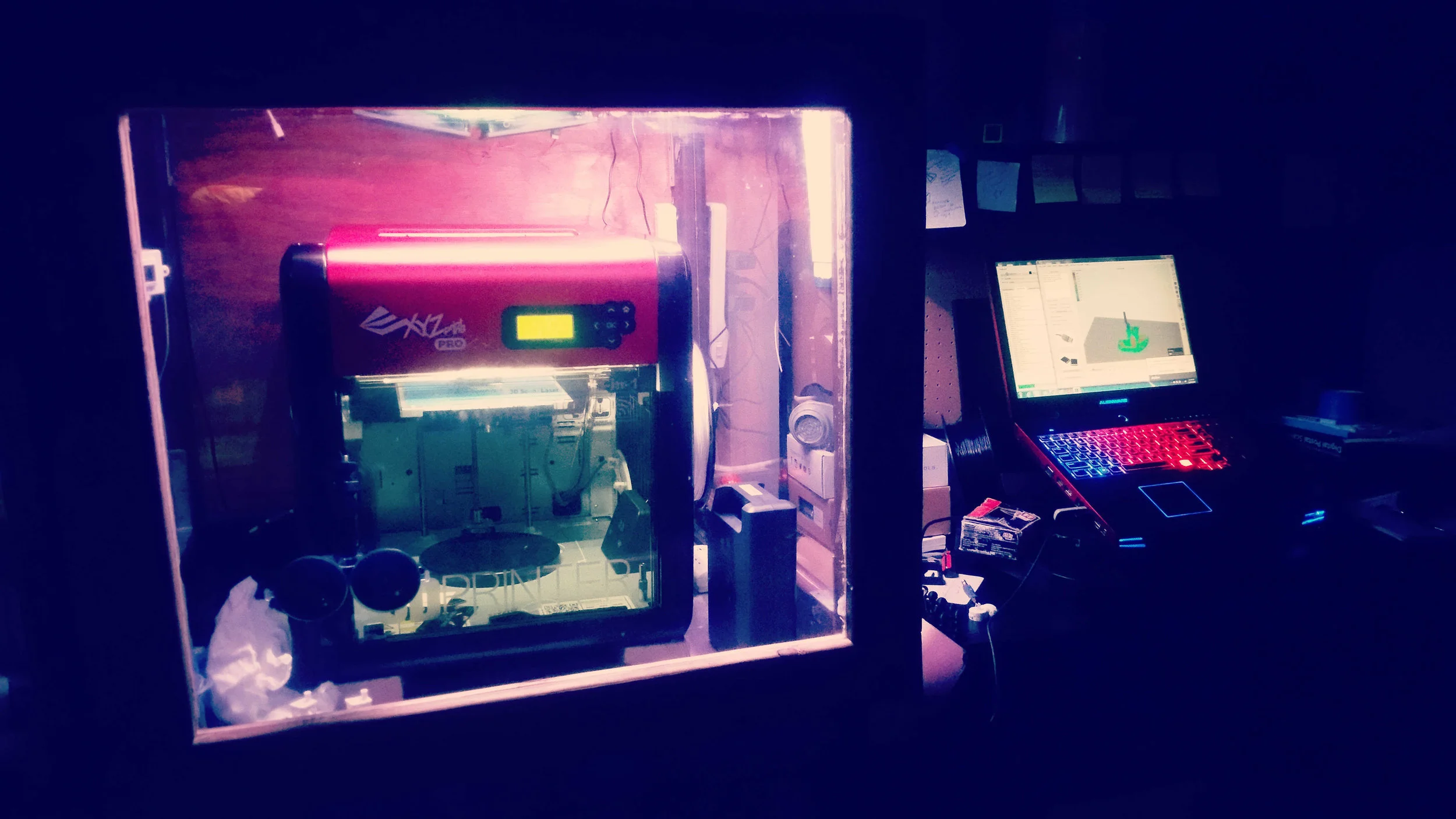
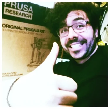
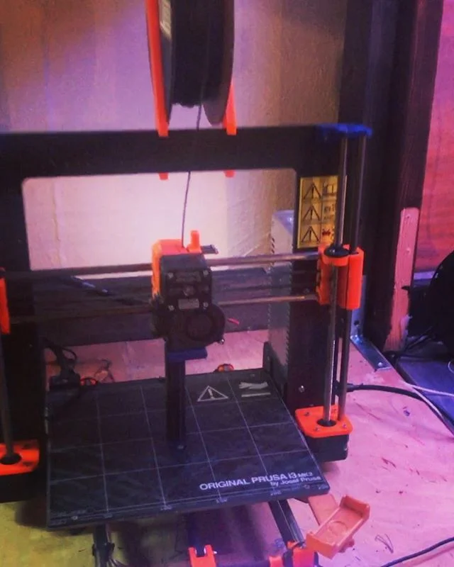
The initial idea was to create a Pokemon-Stadium-from-Super-Smash-Brothers themed Chess set. I had just received my newest 3D Printer, the Prusa i3 MK2 and with it came lots of upgrades and abilities. One of which, was the ability to print parts in multi-color.

MULTI-COLOR 3D PRINTING:

For desktop 3D printers, it’s possible to print more than one color or material in the same print. Essentially, a piece of G-Code is added to specify which layer(s) of the part you will change color or material. (G-Code, for those who are unaware is the language of the 3D Printer that contains instructions to make all the moves, temperatures changes, and extrusion of material needed to make the part).

For multi-color 3D Printing, the printer needs to stop printing and move the hot extruder away from the part, so you can change the material. In this case, I just needed to change colors. But you could also print other materials, even a water-soluble support material that would make support removal effortless.

Prusa Research makes the whole process of changing 3D printer language easy because errors in your g-code could be disastrous for your print if you don’t do it right. Simply add the g-code you want, and select the height where the printer needs to change material. The hardest part is finding the right layer height to choose. I found a nice simple way to figure it out.

First, take your layer height (.2 mm in this case) and then multiply it by the layer number (easily found in Simplify3D during print preview. Simply slide the END bar to the layer you want to change). That will be the number you need to set the G-Code to. It will also be your first change of color, so make sure it’s where you want it.

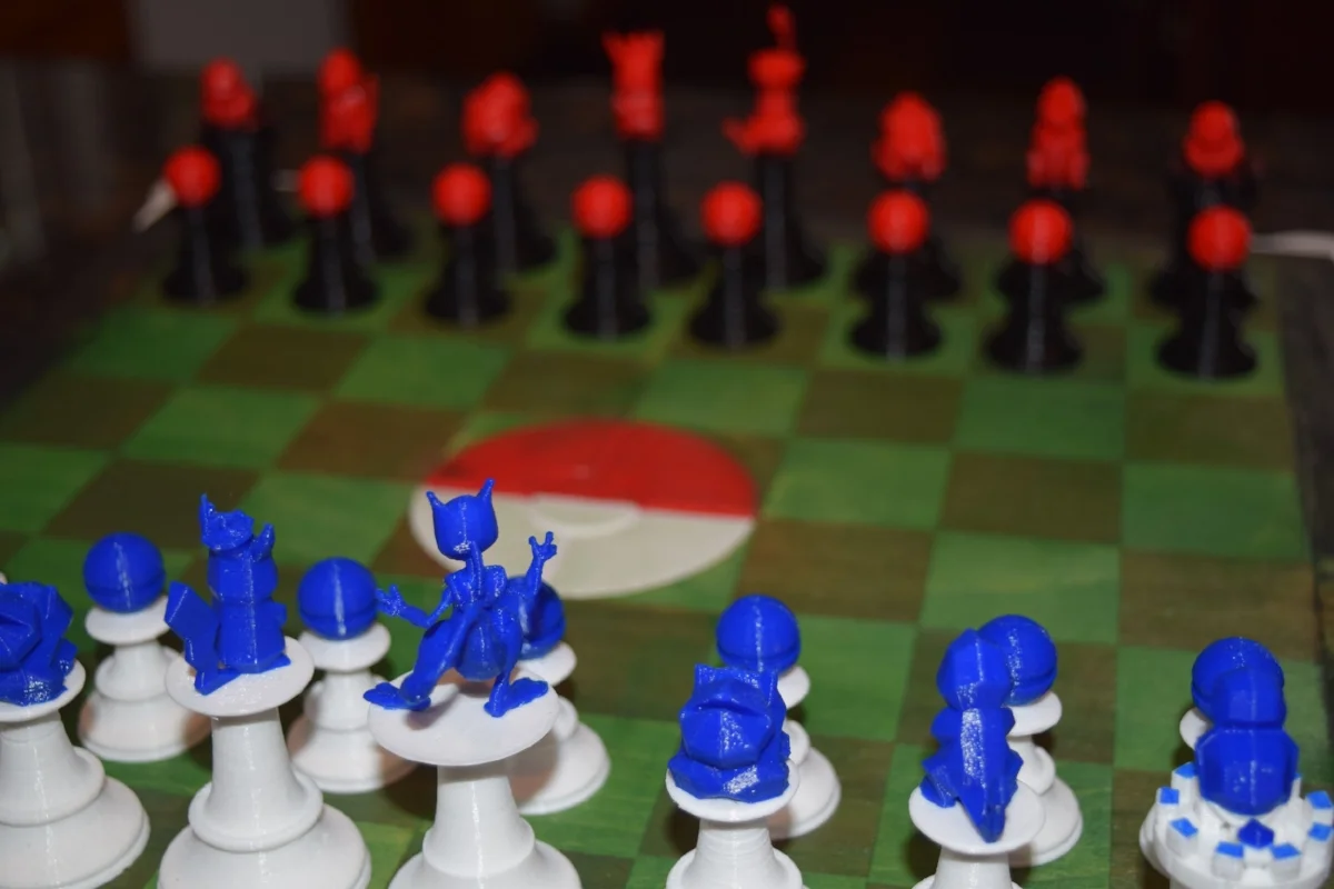
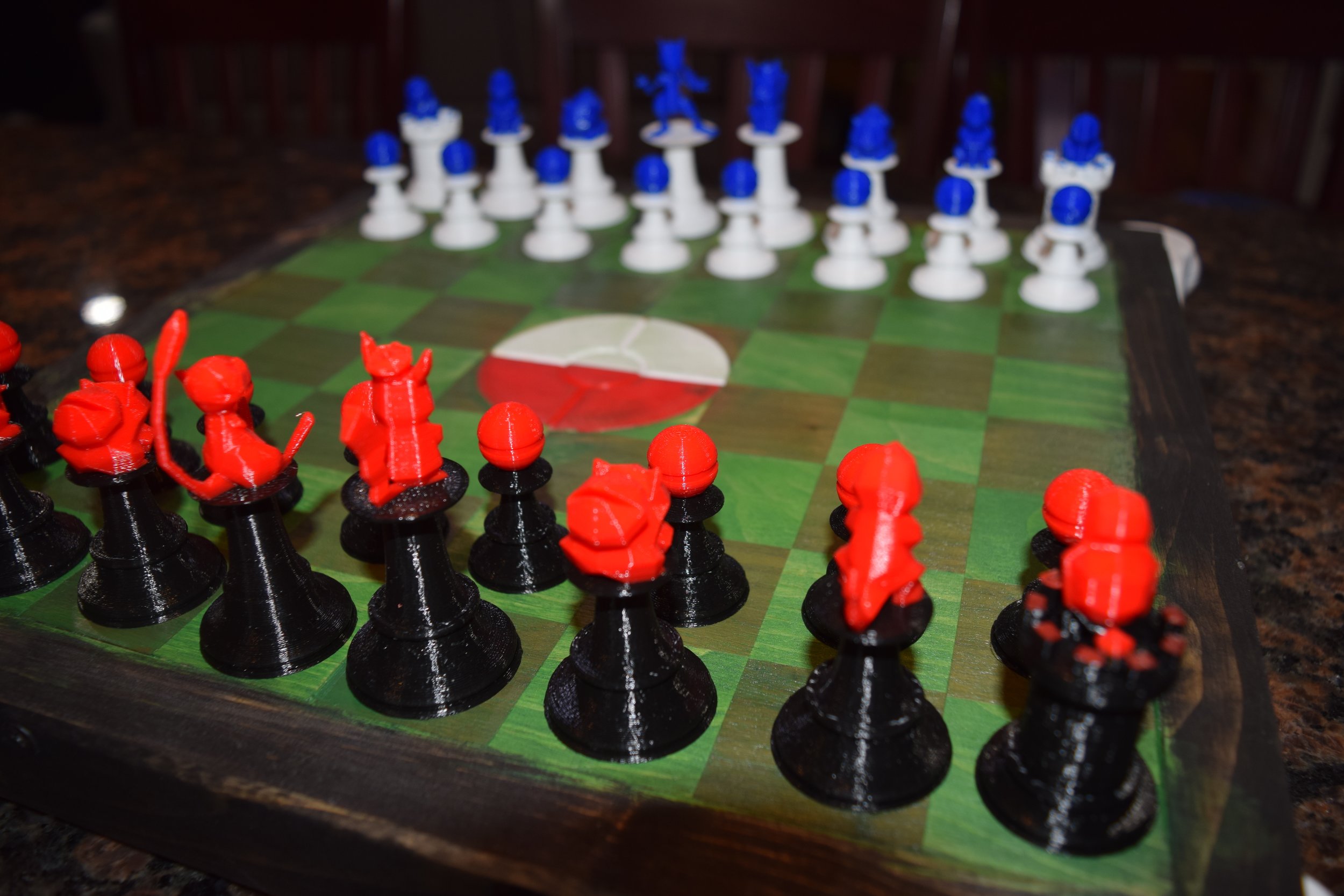
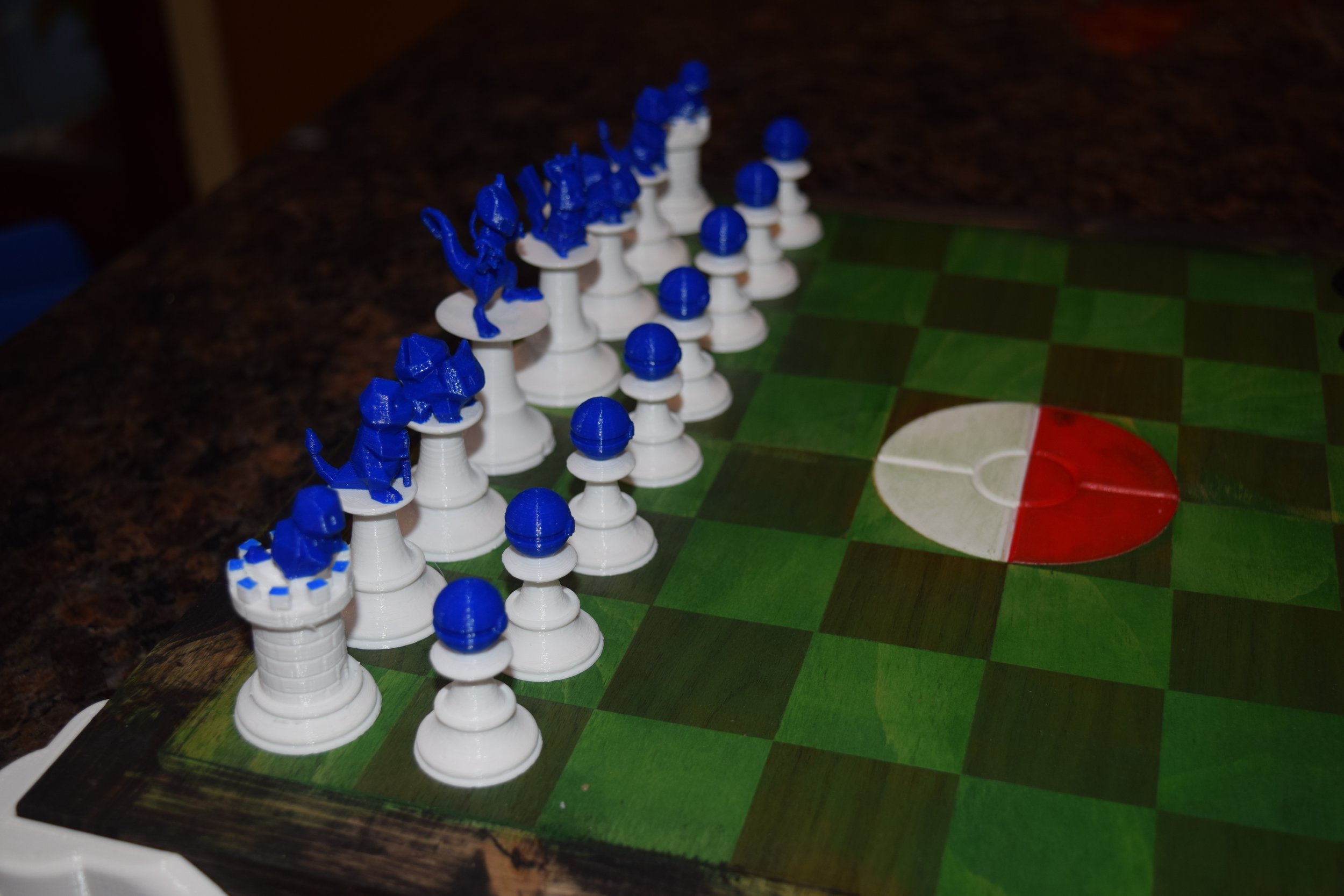
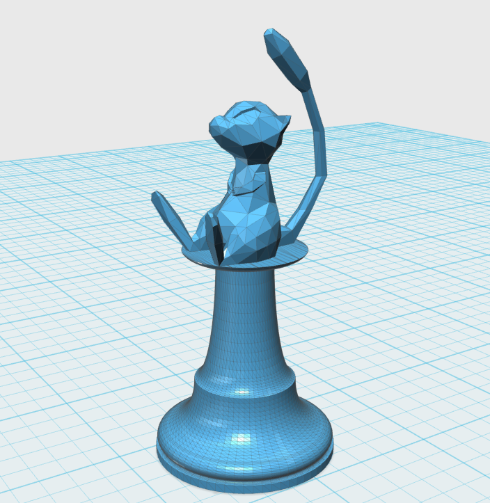
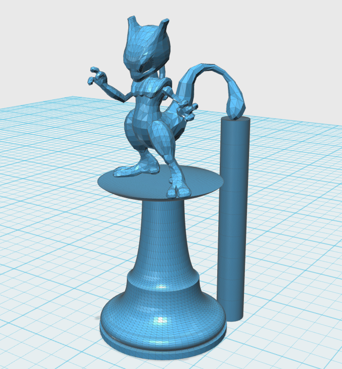
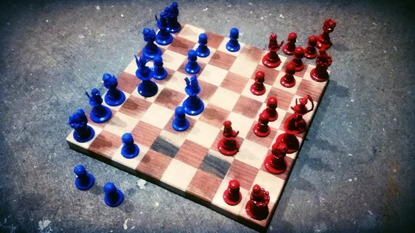
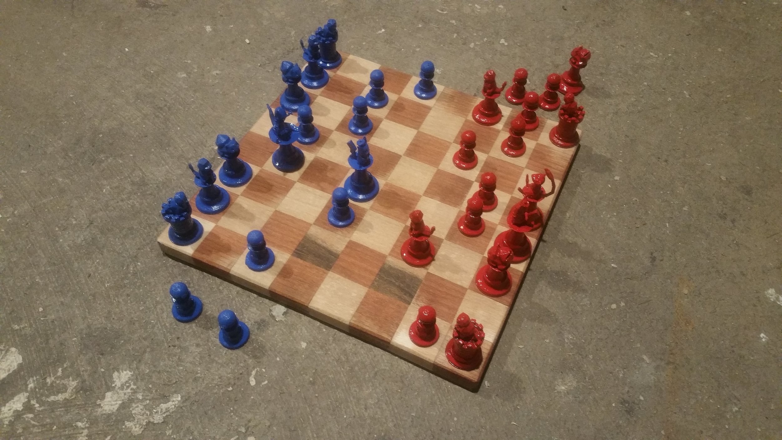
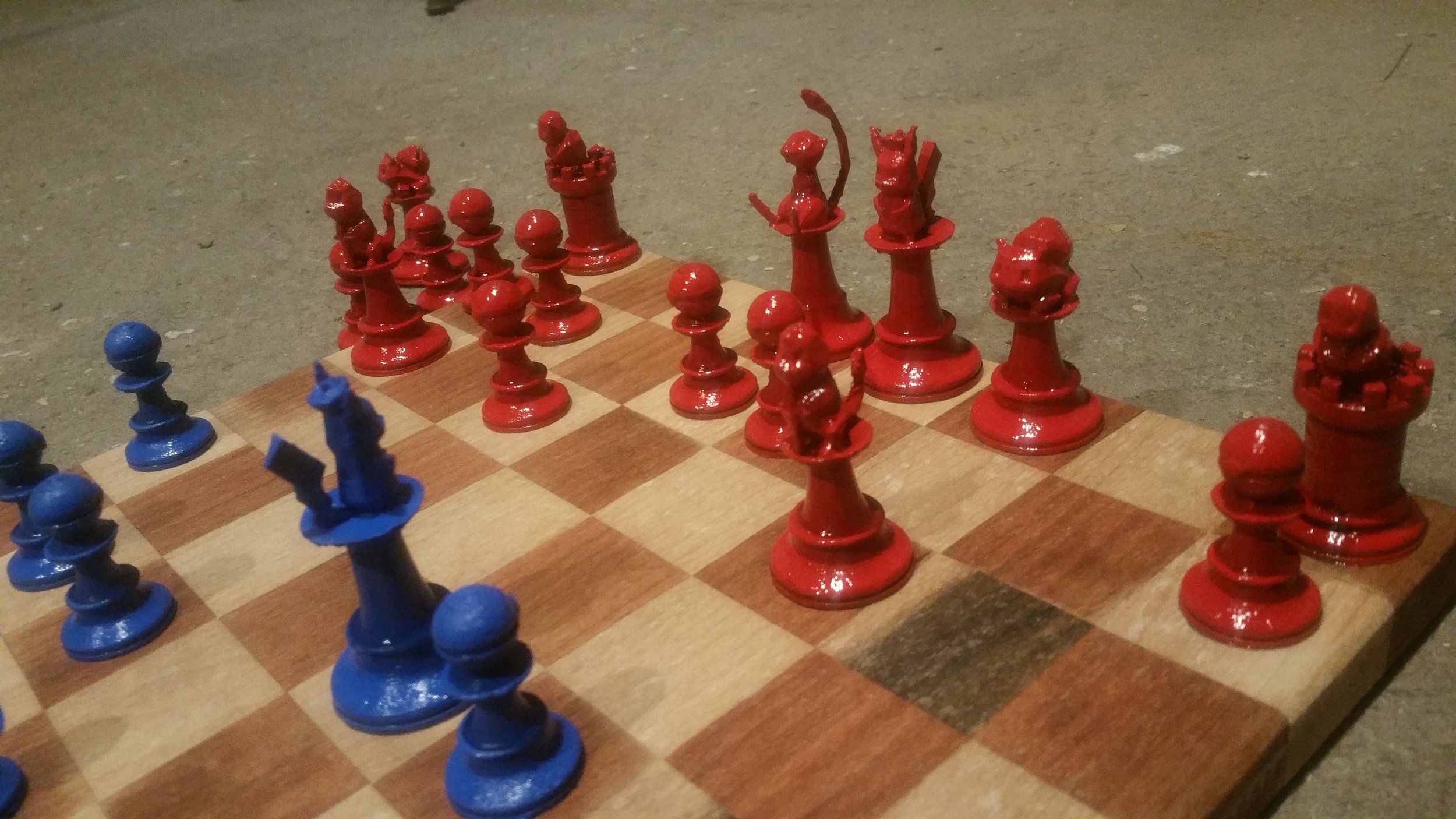
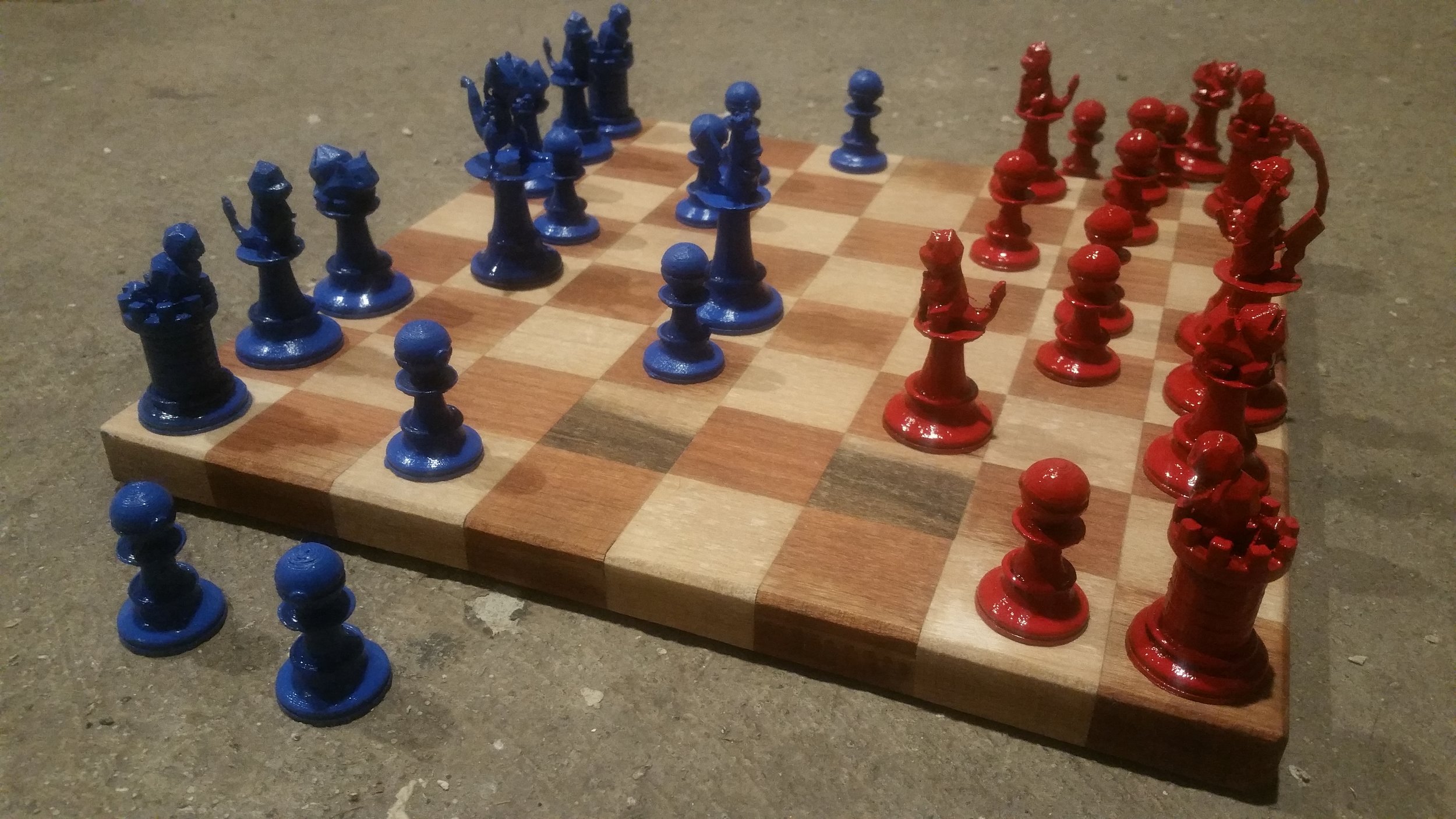
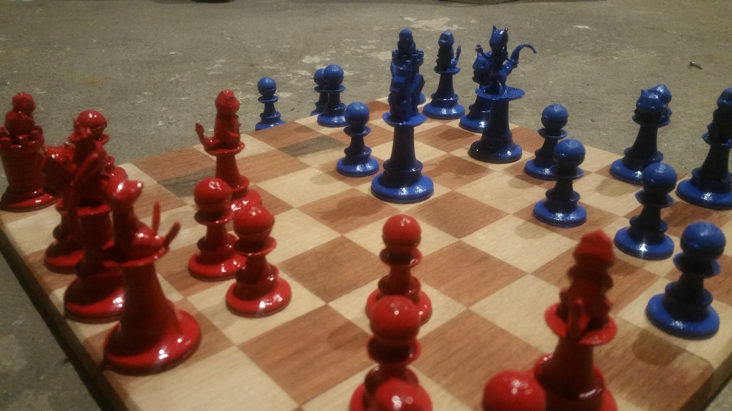
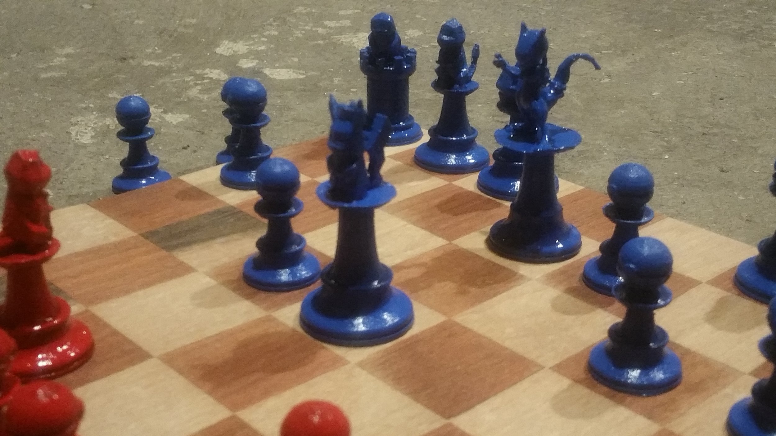
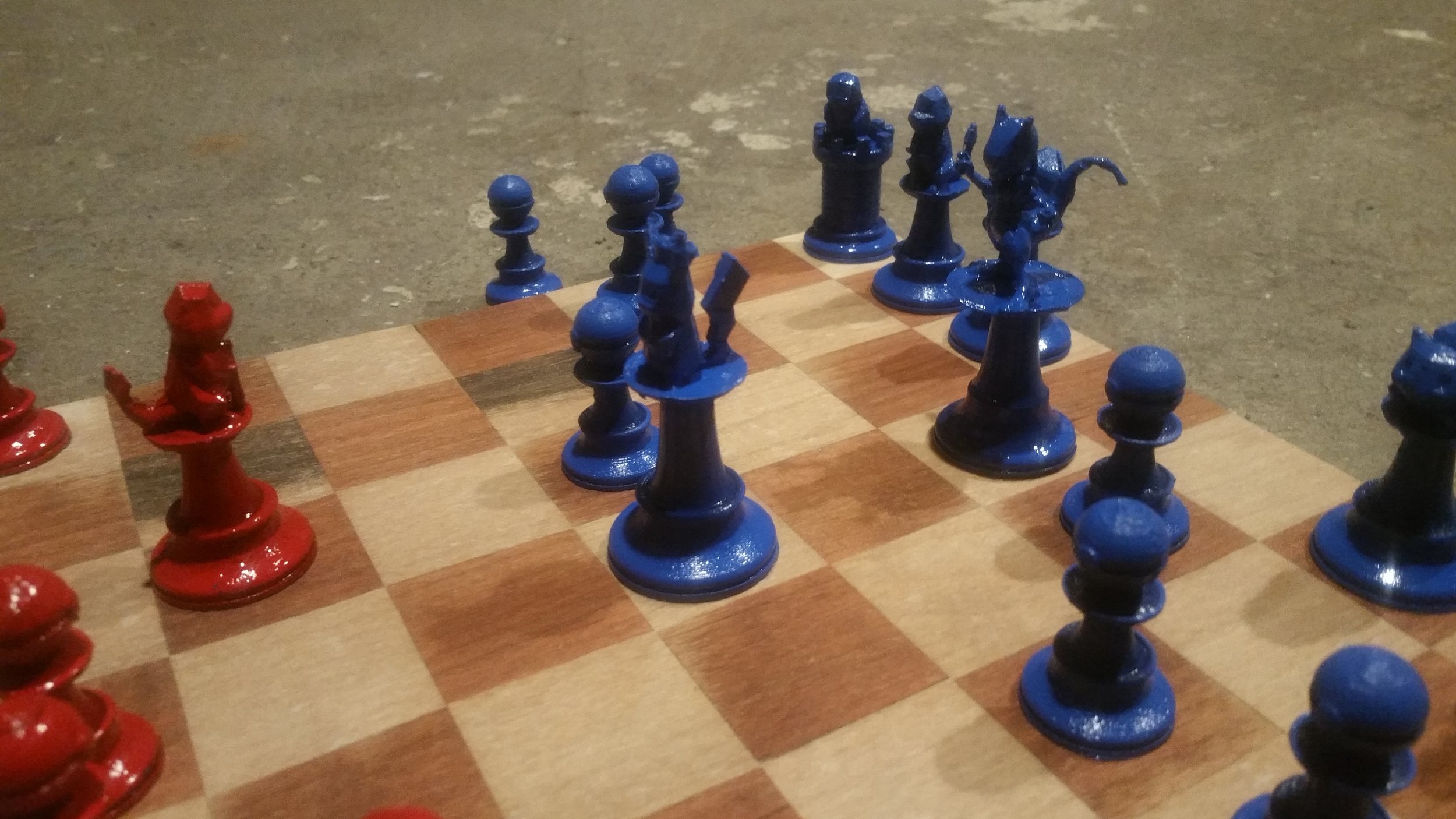
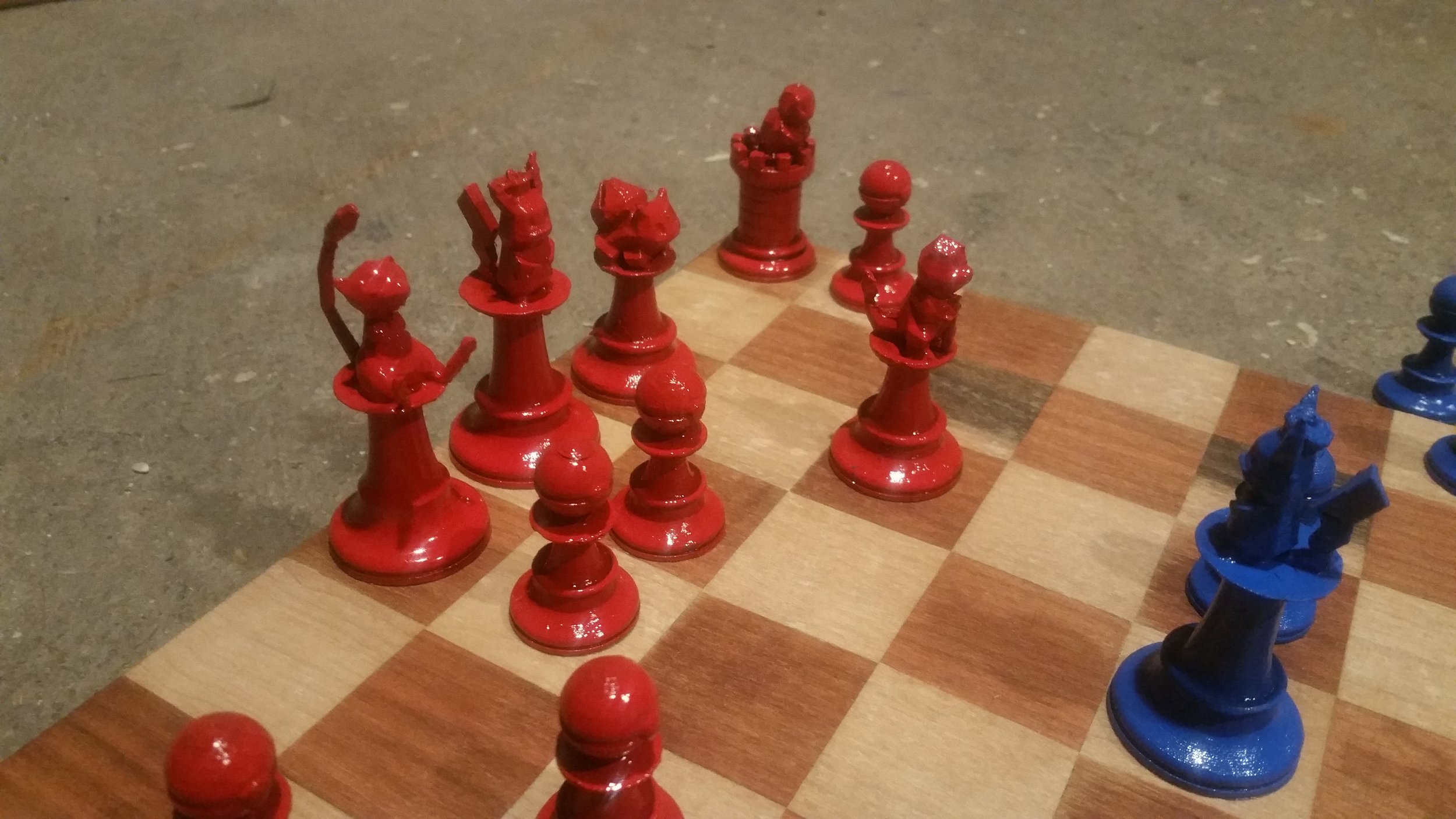
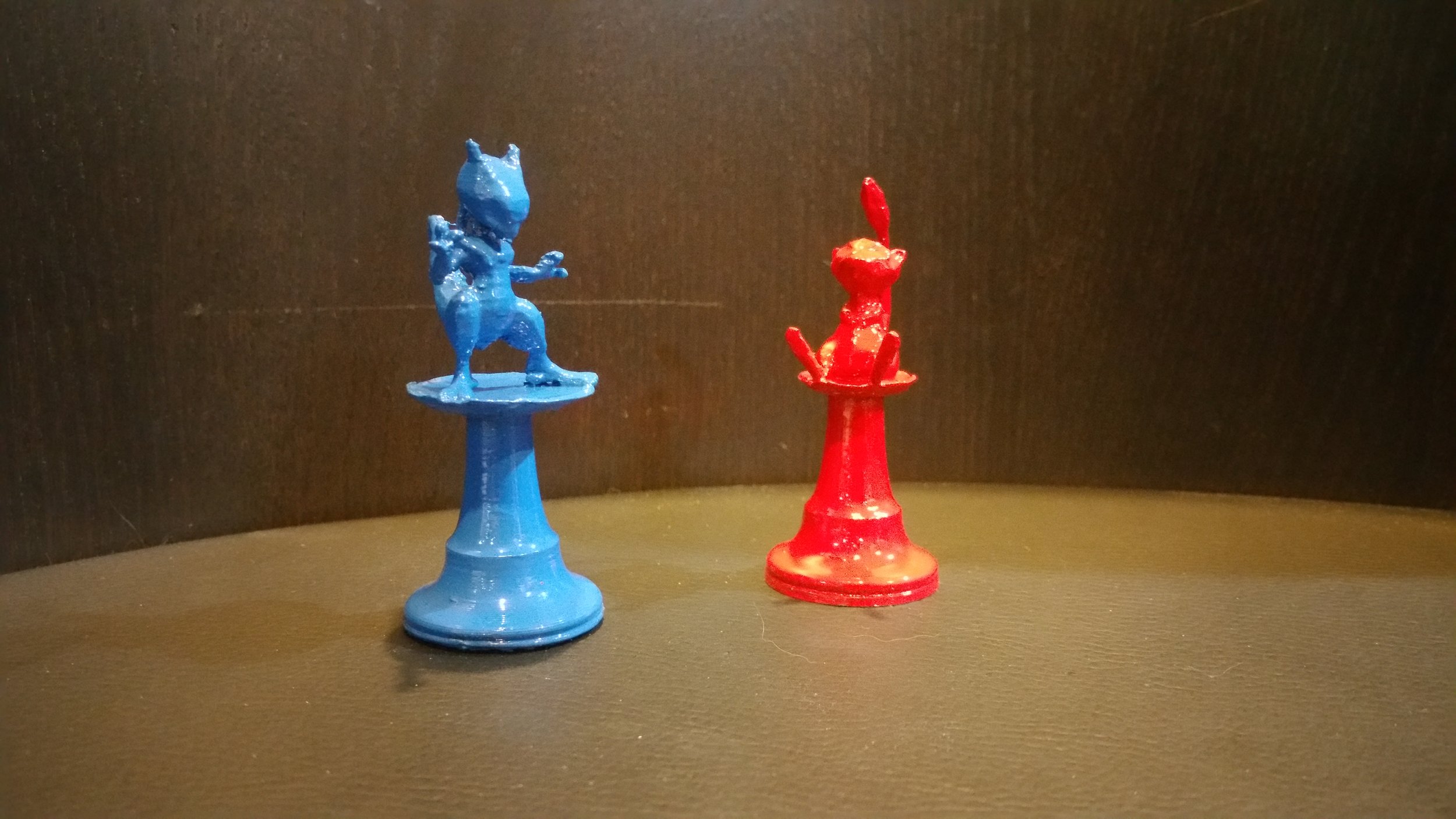
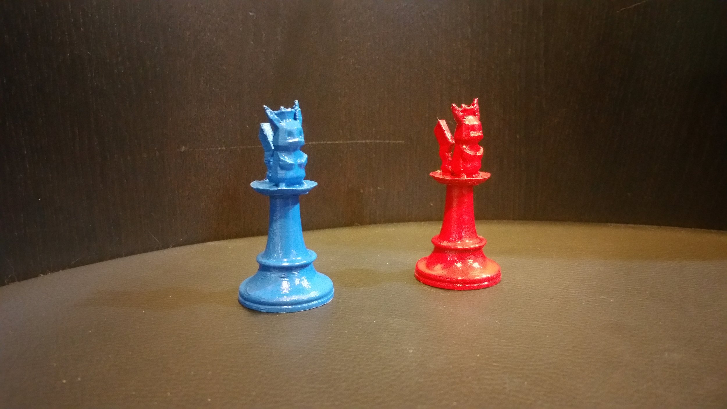
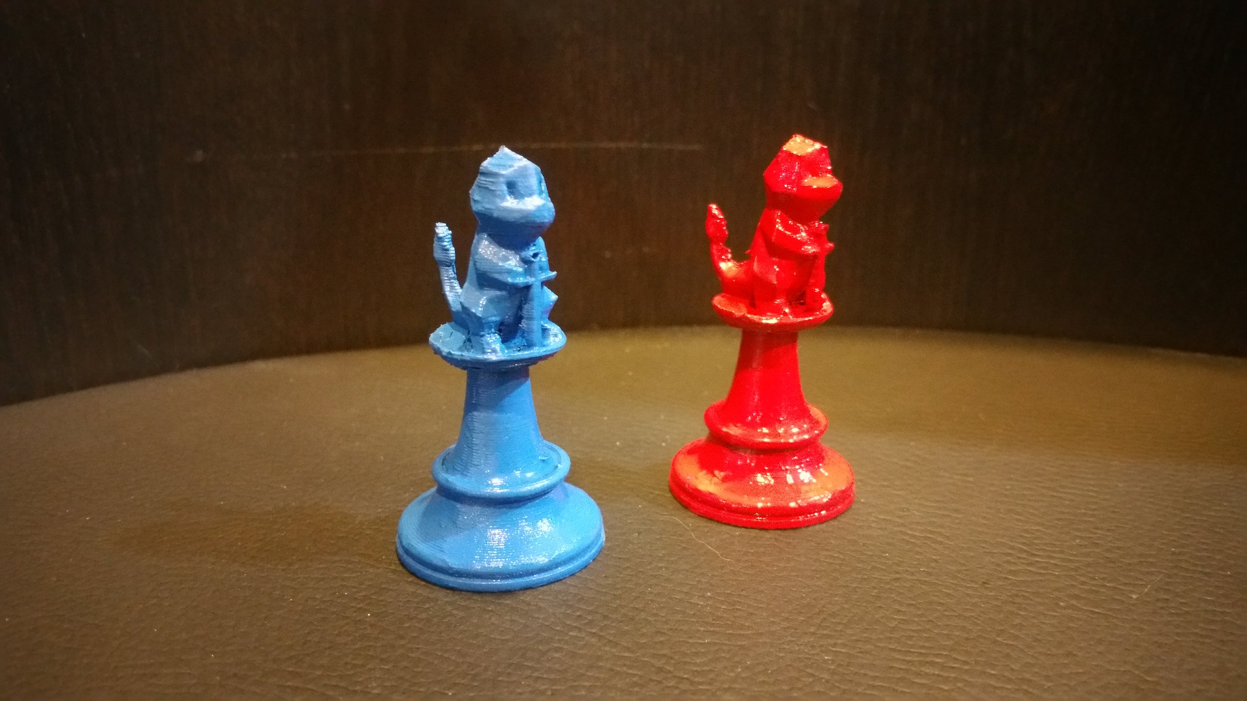
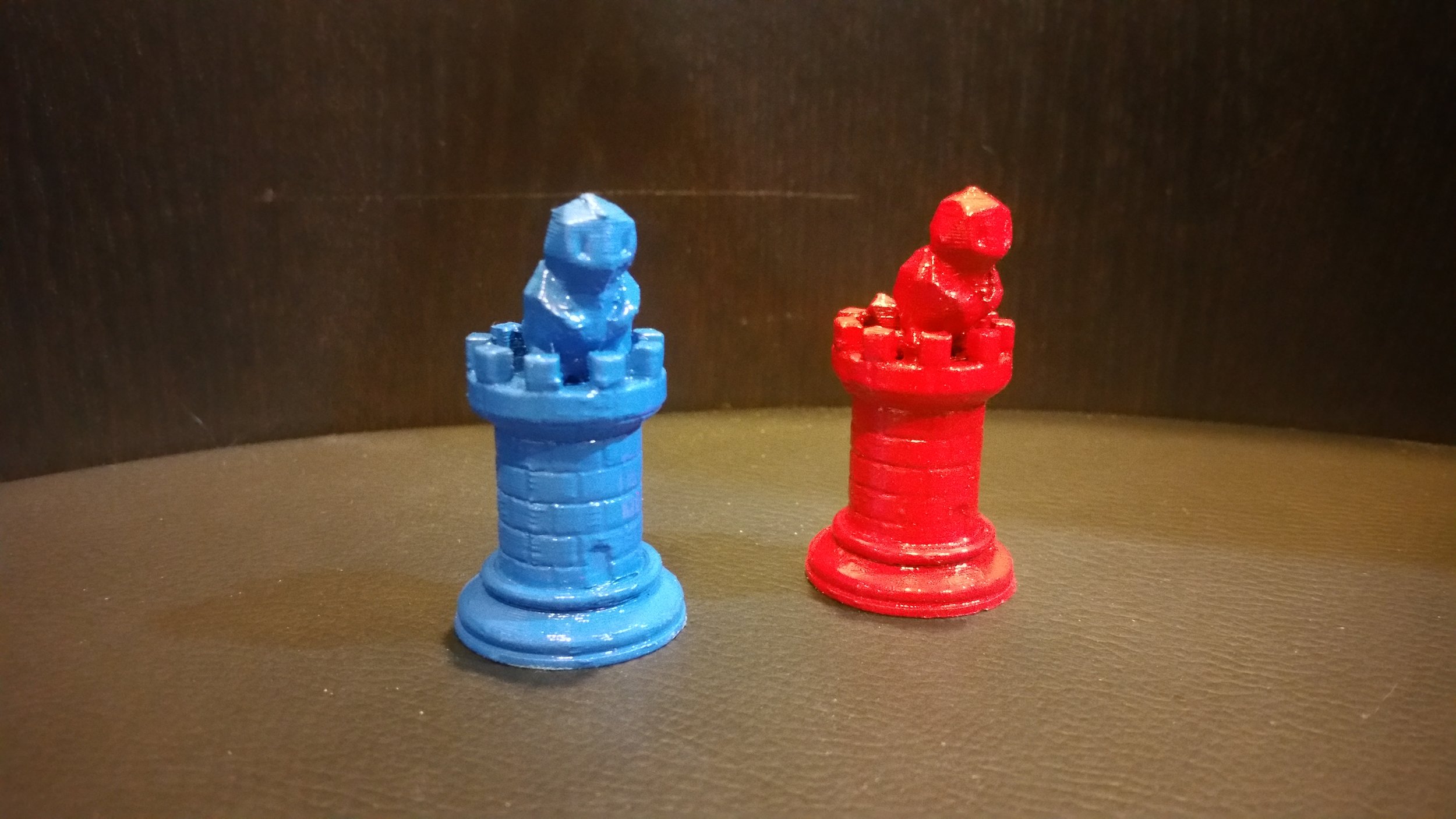
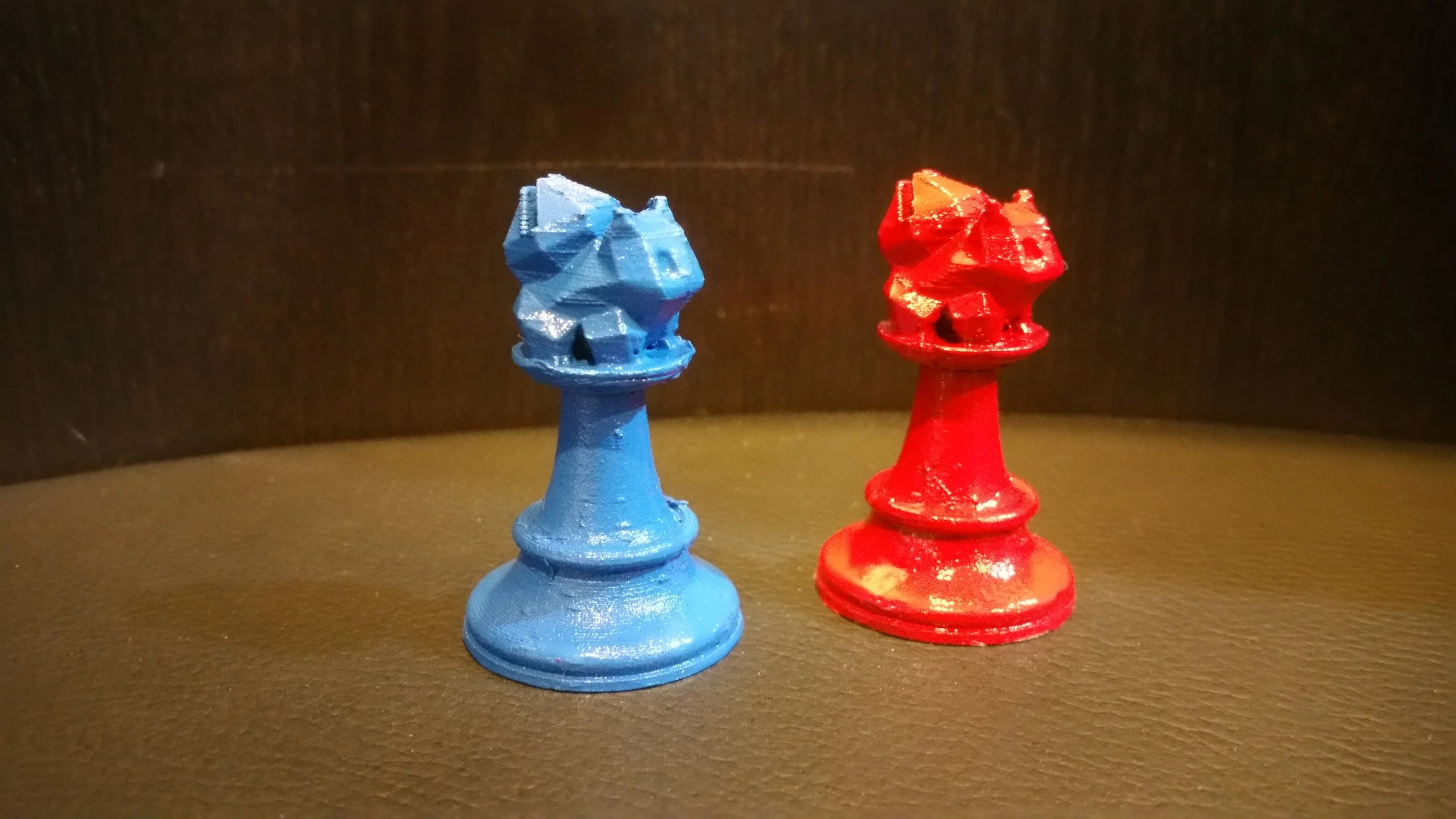
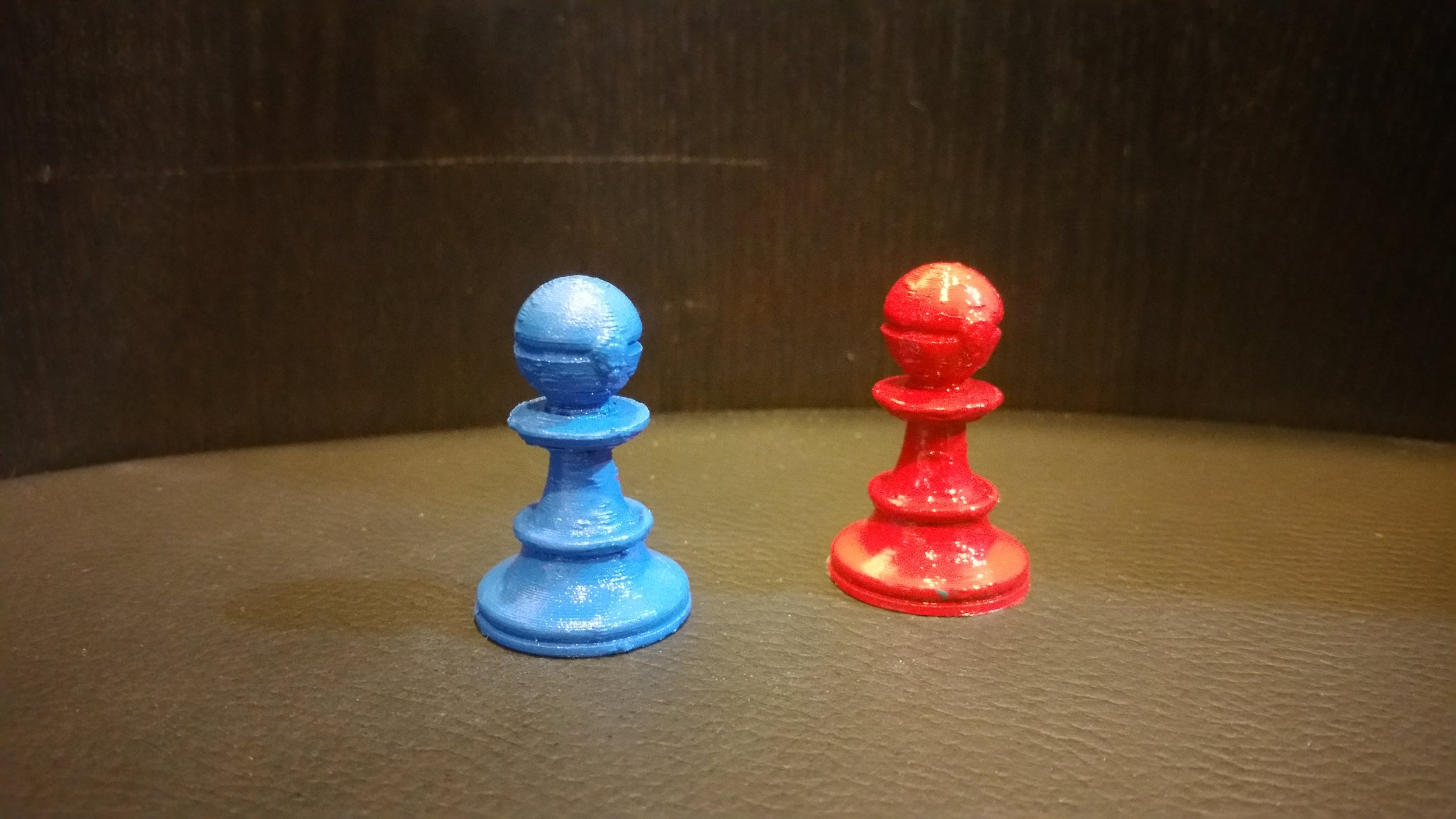
For me I wanted each Pokemon to be a separate color from the chess piece body. So I set the color change layer to the first layer of the Pokemon’s body. The cool thing was this meant I could use the same G-code for both color pieces. All I needed to do was start with white/black, and then change to Blue/Red when prompted. A nice buzz goes off when I need to change the filament. Easy.

3D PRINTING IN BATCH:

3D printing in batch is what I call 3D printing multiples of the same objects at the same time. For example, with the chess set all I had to do was create one multi-color g-code file for both the Red/Black and Blue/White pieces. All I needed to do was start with black and change to red, or start with white and change to blue. This made the whole process a lot easier, and saved me ALOT of time compared to changing colors for each of the two sets of 16 pieces of the chess set. I only had to change colors x12 times for the whole set to be created (as opposed to the REALLY inefficient way of changing for each piece, which would be 32 times. Not ideal).

3D PRINTING PARAMETERS:

The parameters stayed the same from the first Pokemon Chess Set, and are based on the original setting laid out by the creator of the chess set on Thingiverse.com (roshandp1)

INFILL %: 10 (RECTALINEAR)

LAYER HEIGHT: 0.200 mm (Normal)

SUPPORTS USED: YES

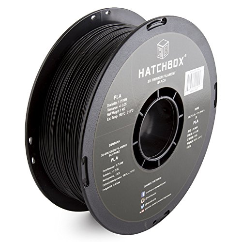
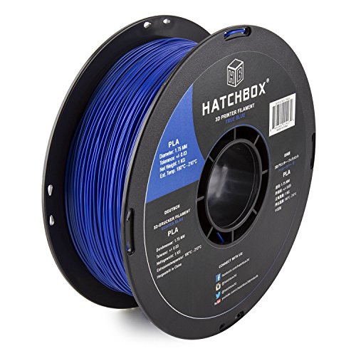
But I did not require rafts to print these, and the bottoms came out nice and smooth. Glue stick and a 60*C bed temperature was used to ensure the PLA would remain secure during printing.
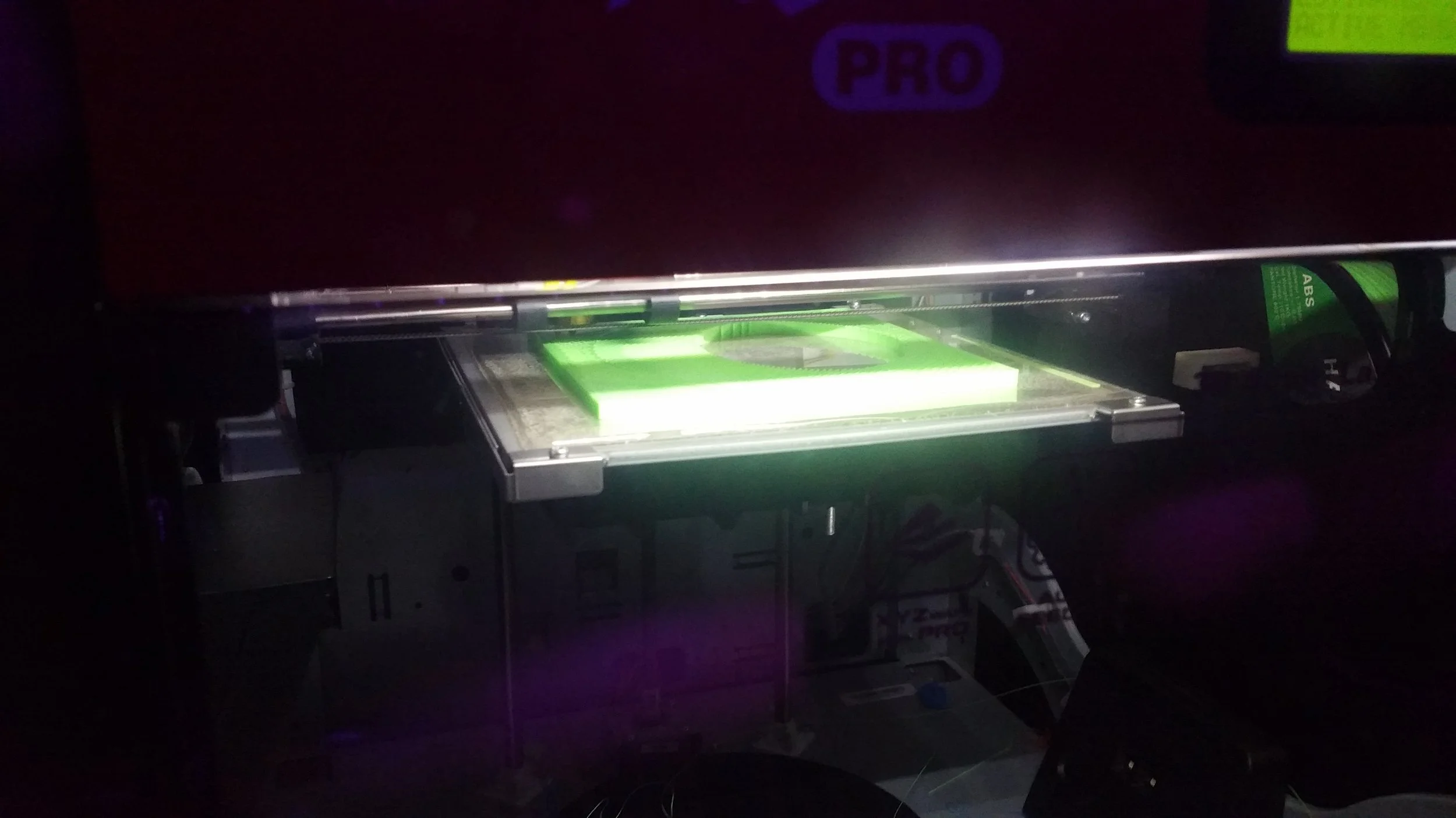
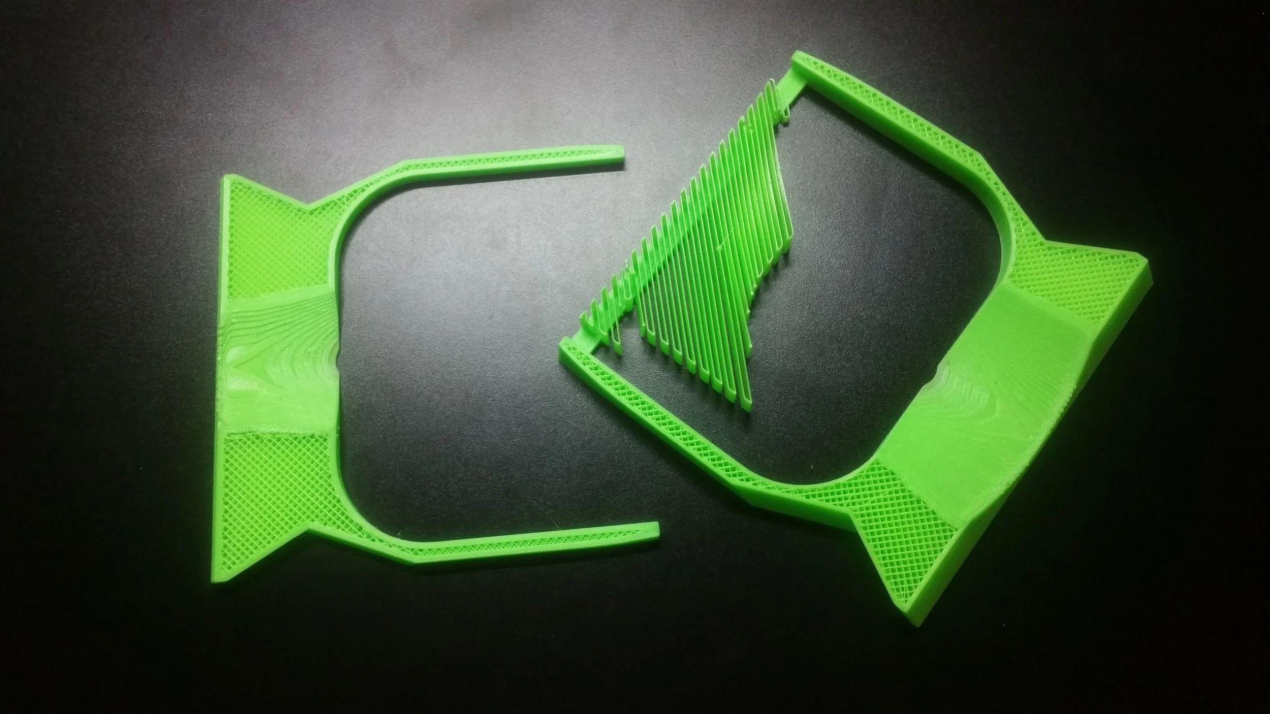
3D PRINTED INSERT:

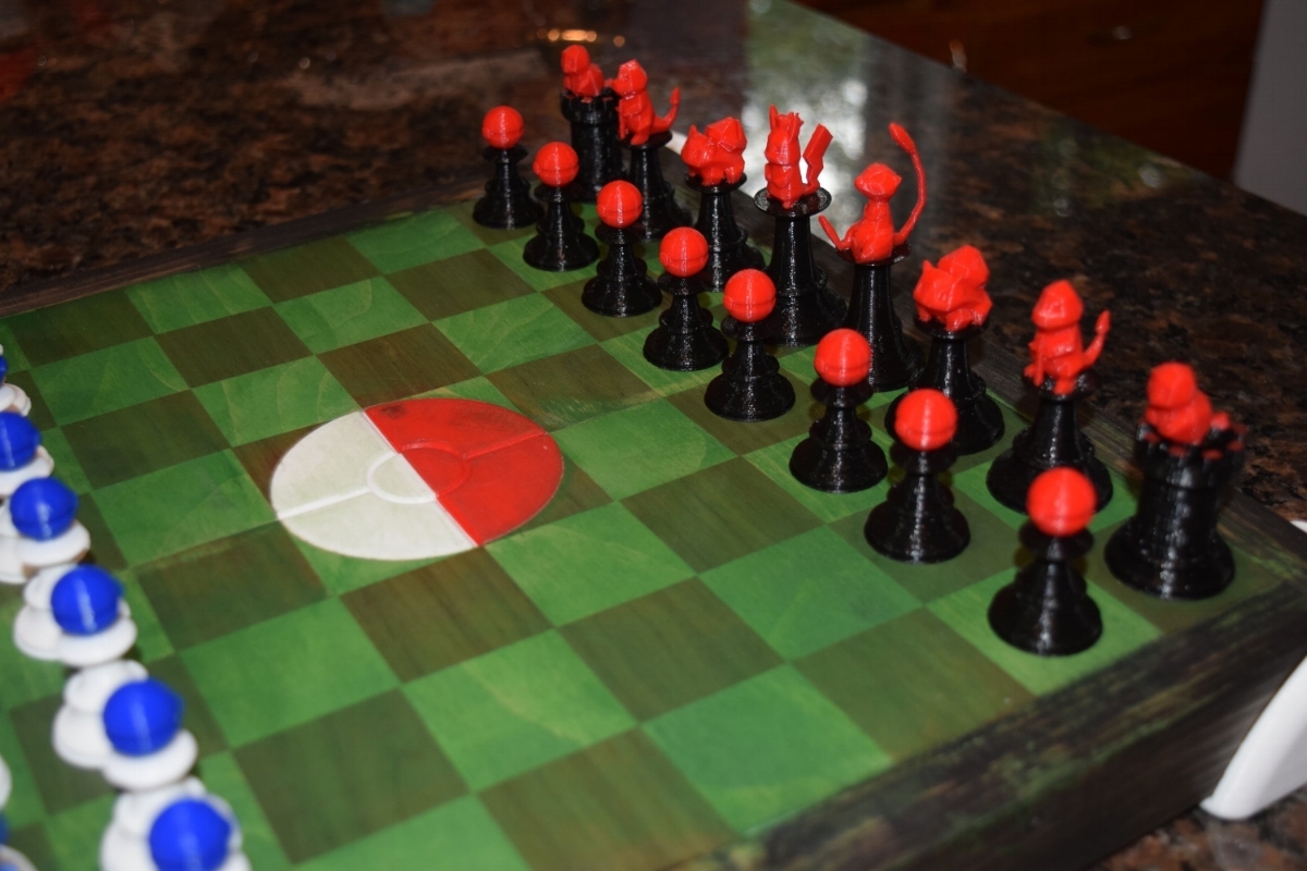
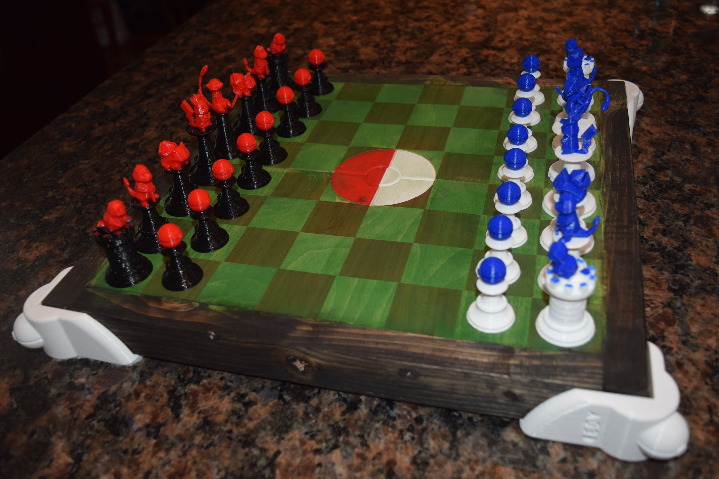
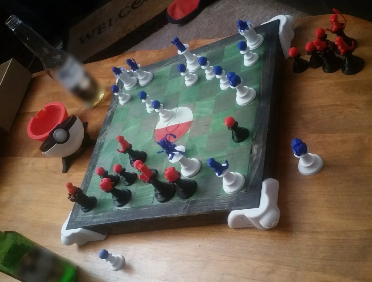
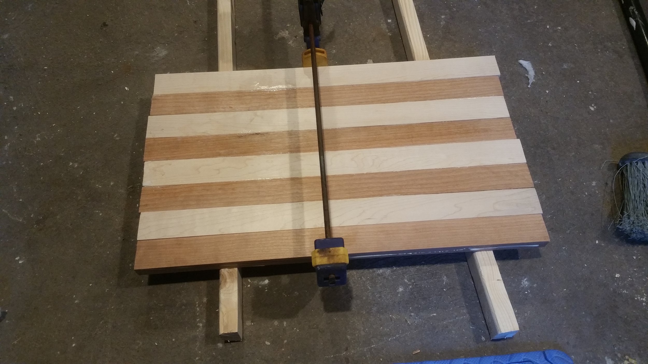
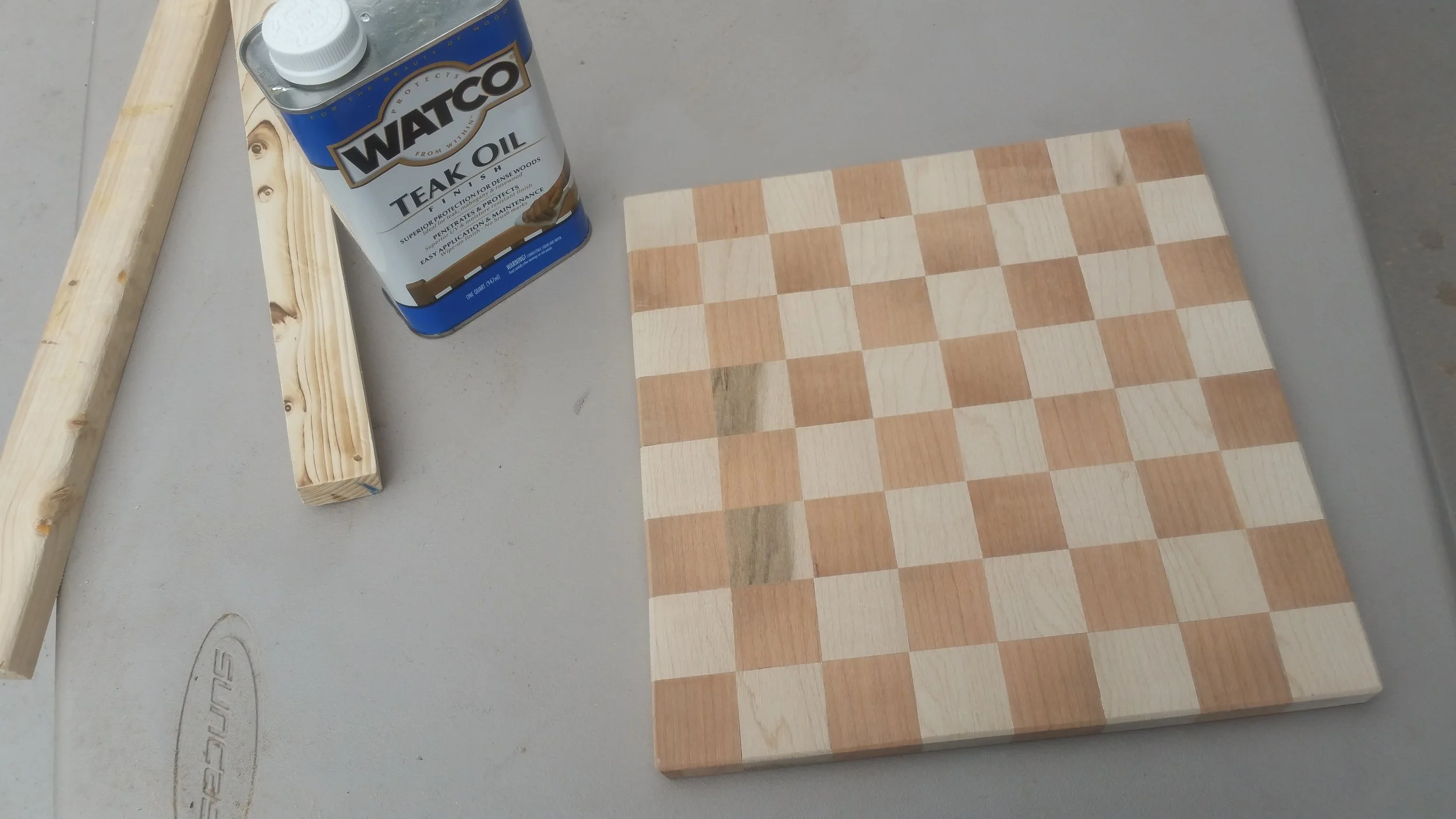
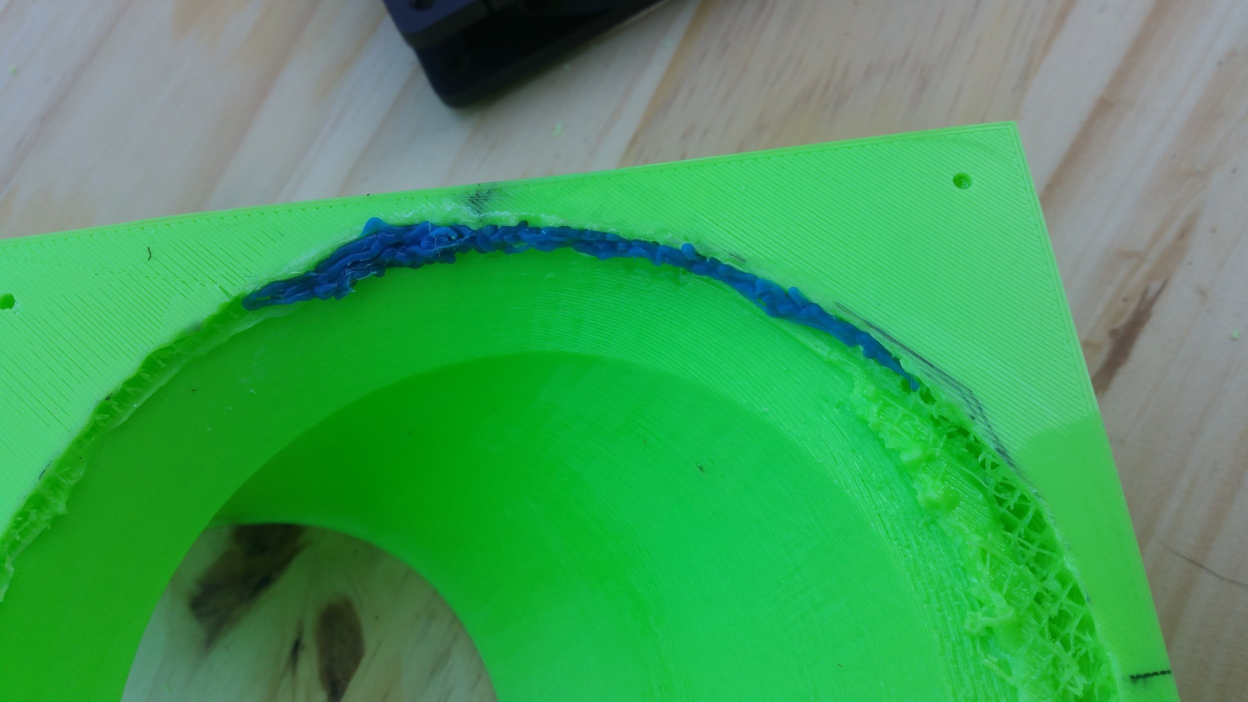
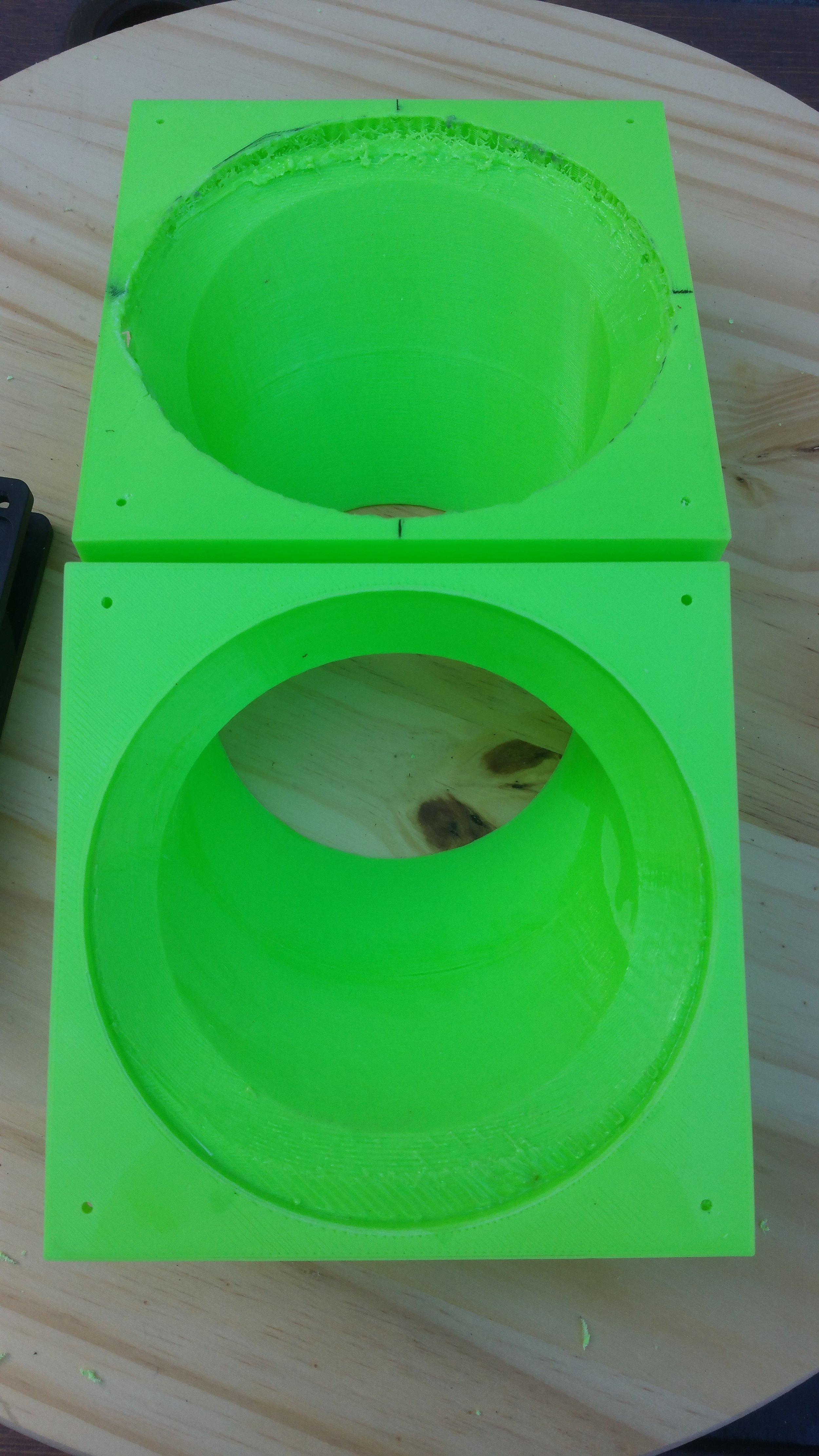
In order to create the Pokemon Stadium look, there needed to be a Pokeball in the center of the board. I used a 3" hole bit for my drill and created the hole in the center of the board, after it had been bonded together. I then designed and printed two different, almost symmetric pieces that I bonded together and pressed into the center of the board.

Next time, I will make the 3D printed piece slightly smaller than the hole, and not exactly 3". I assumed the plastic shrinkage would give me enough room, but the insert was very tight and required more work than was necessary. All in all, I was very happy with the final look of it and am excited to try out more 3D printed inserts in wood soon.

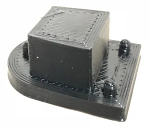
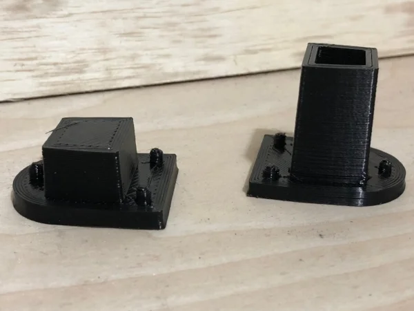
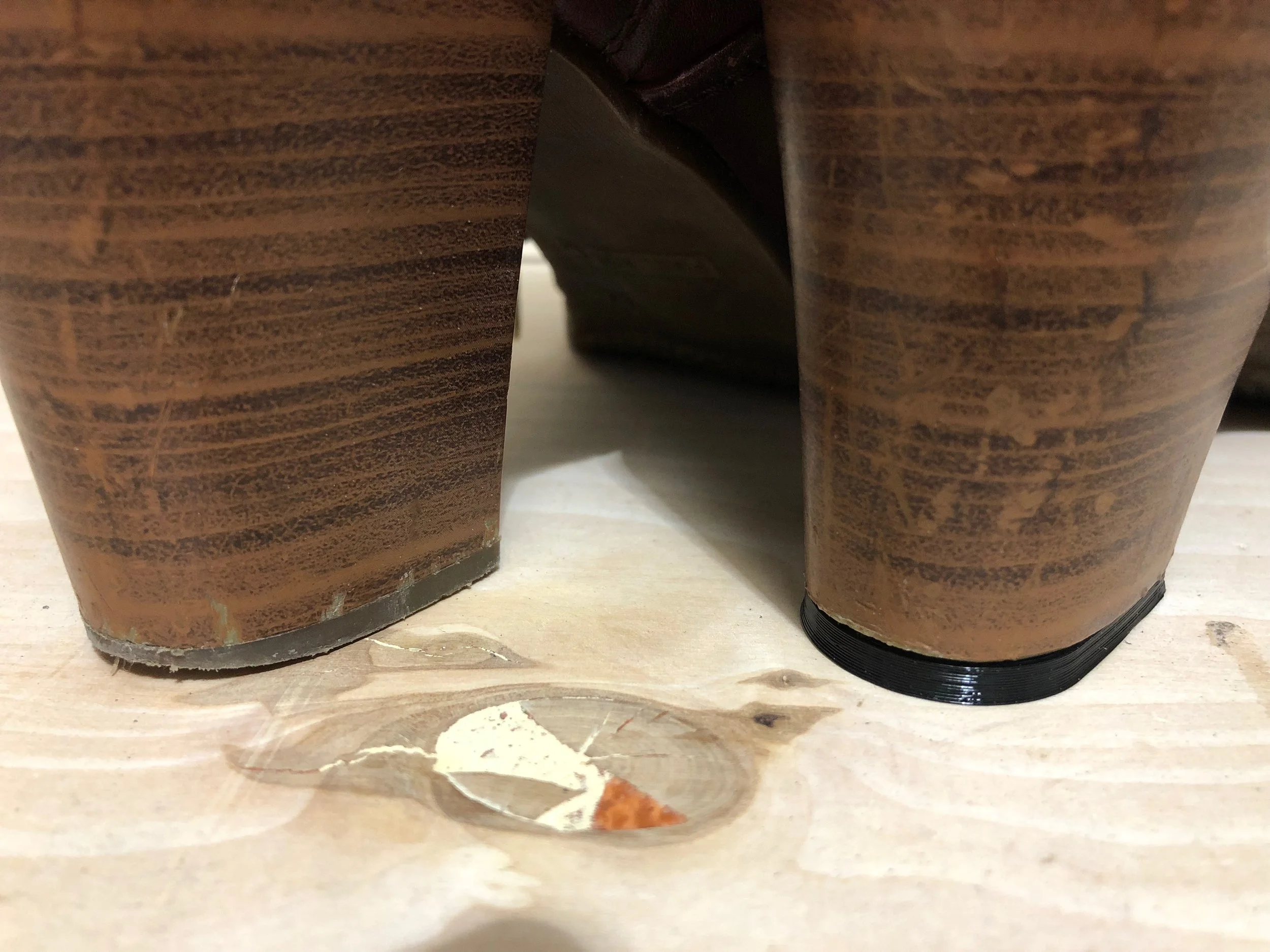
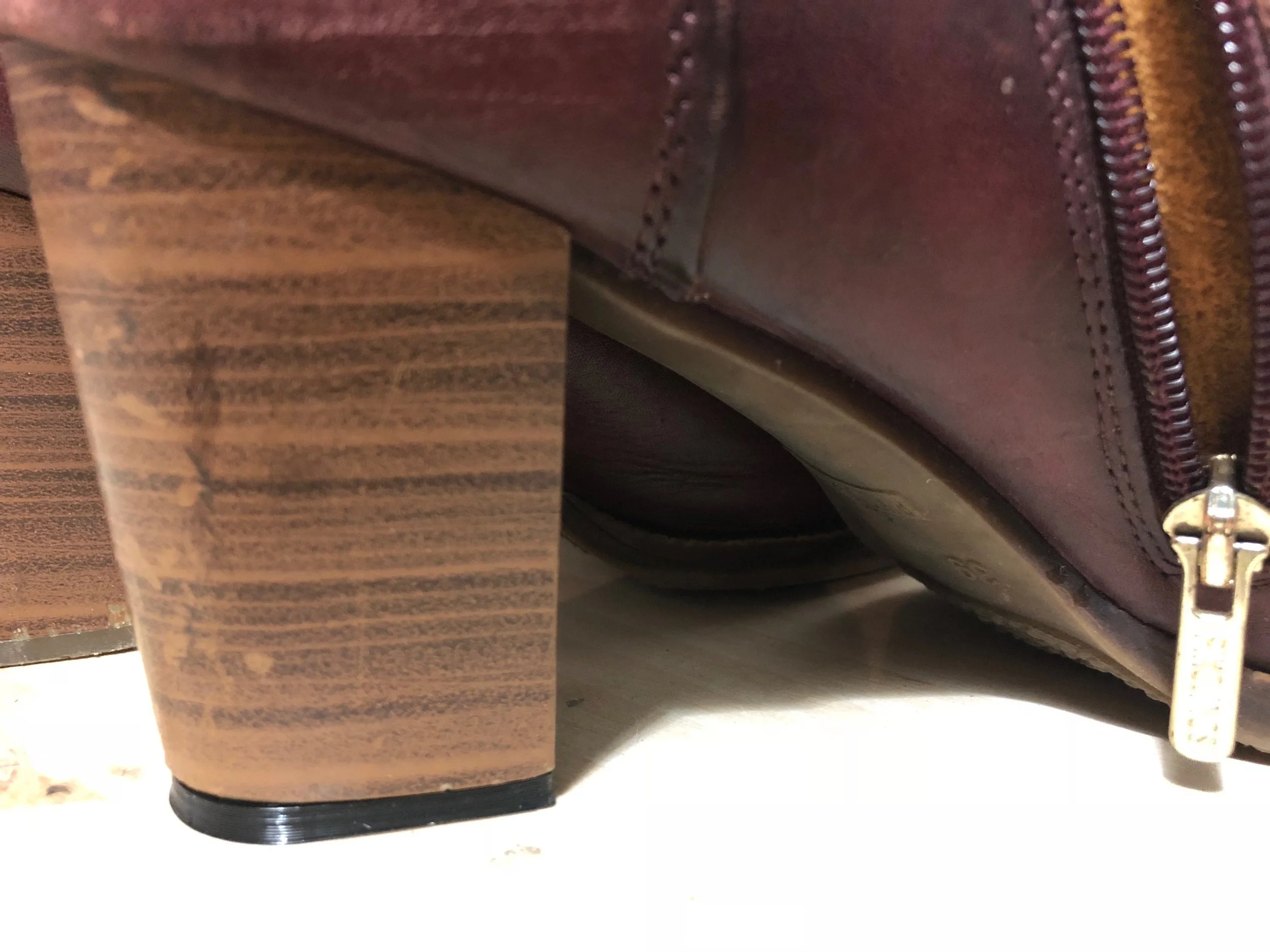
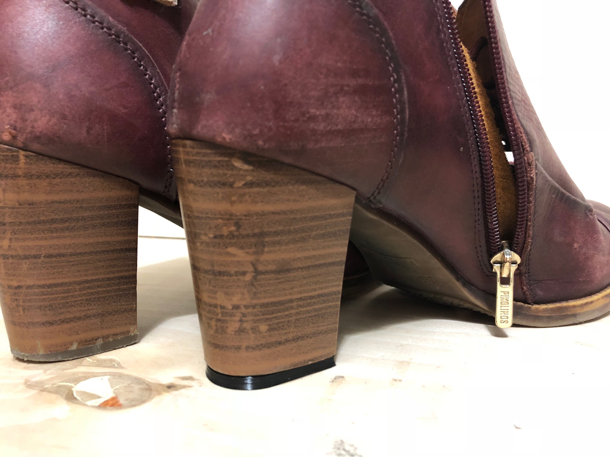
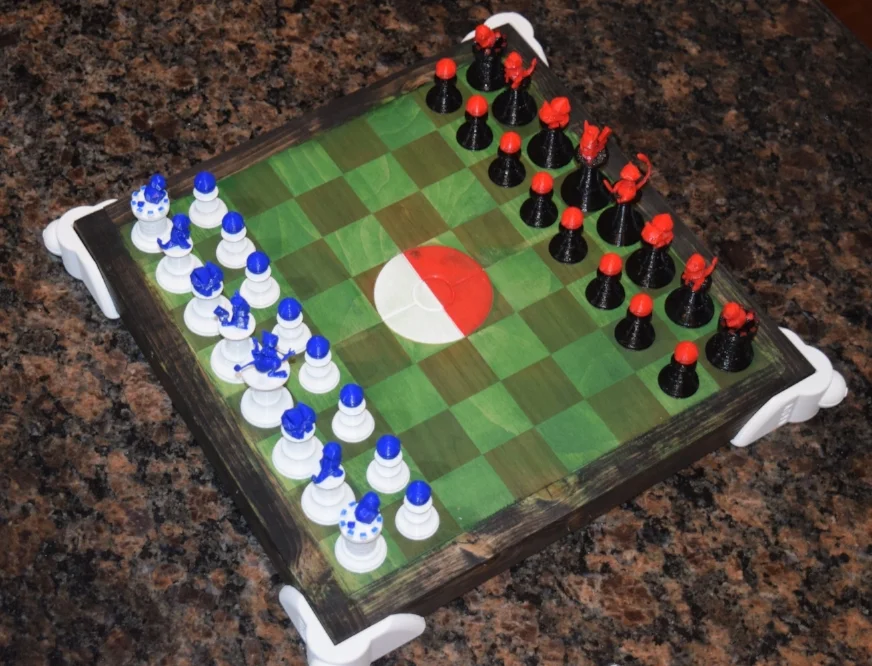
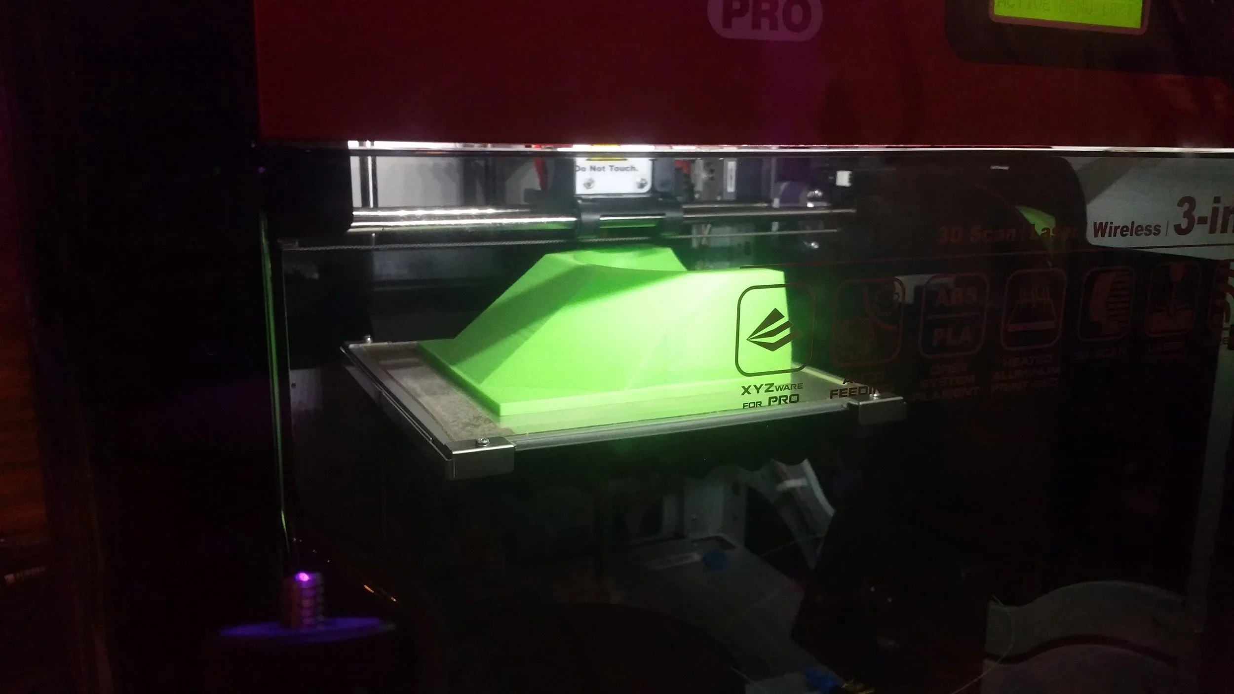
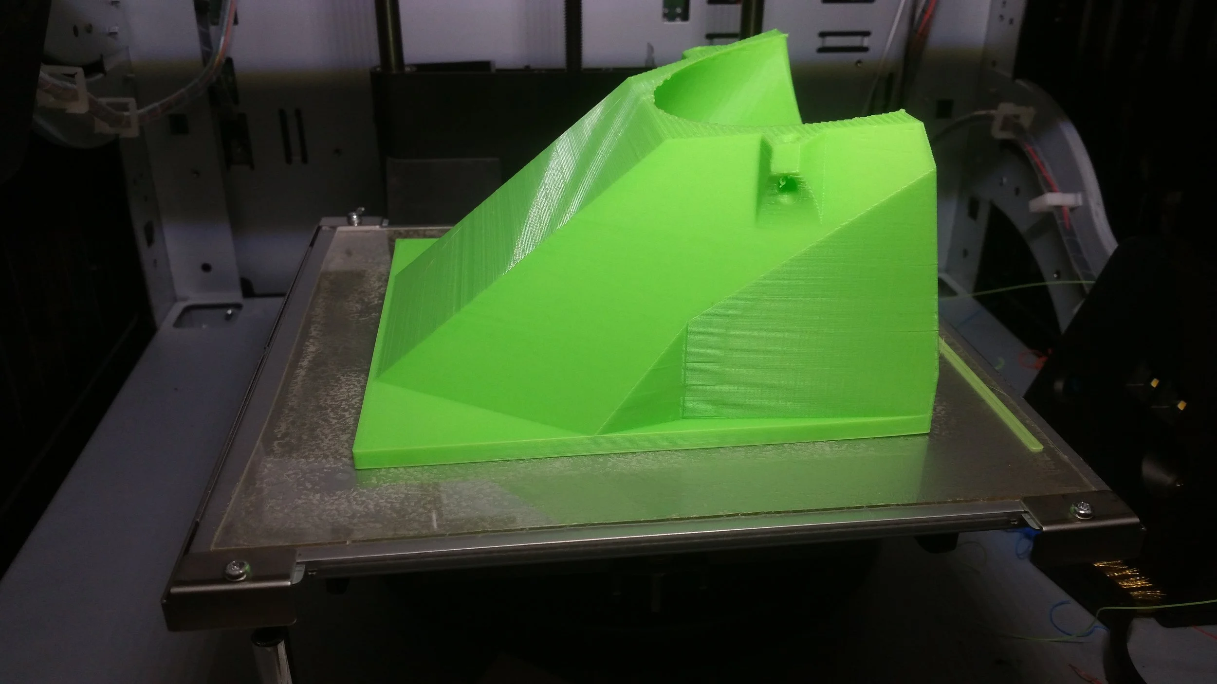
3D PRINTED STADIUM RISERS:

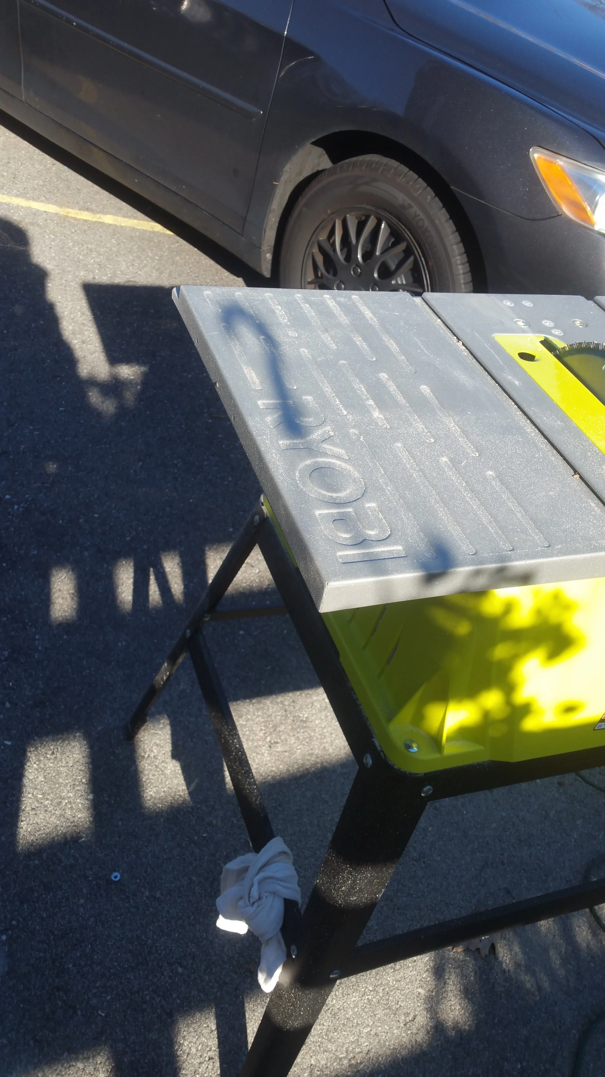
Until my carpentry skills get a little better (and I have more available tools) making something completely flat is difficult when you only have a belt sander. An easier and better looking plan was to create the stadium risers on each corner of the board. I incorporated a Pokeball and my logo in each riser. After some testing, and a little glue and felt, the risers were complete. I realized after that the my logo was visible from every view of the board, which was pretty cool to notice when it was done.

CHESS BOARD UPGRADES:

One thing I learned from the first chess board was that anyone could make a chess board, but it's the style and extra work put into it that makes it special and unique. This time I tried a board with both hard wood and light wood, that brought some of it's own challenges but came out nice in the end. The light wood absorbed the green stain perfectly and created a grass/dirt field look to the stadium, giving it the appearance of being worn and used.

I used a more abrasive grit when sanding the board this time, because try as I might, when you bond the strips of wood together to make the boards checkered look, it gets uneven. I sanded the surfaces to a smooth, almost unified surface this time. I also added a board strip of wood with a different color to frame in the whole board and make room for the risers to be used. This also added to the weathered look of the stadium.

THOUGHTS ON PROJECT:

This project was challenging and entertaining to make. I enjoyed working on it during each step of the process. So much so, I am now offering Custom Chess board and set making from AG3D, so contact me for details if you're interested (ag3d.engineering@gmail.com). I also was able to extend my abilities with 3D printing VERY far, getting comfortable with both multi-color and batch 3D printing. I also managed to increase what I am capable of with custom chess boards and found a new passion to discover what other 3D Printed inserts I can do in wood.

If you have any ideas to 3D printed inserts, questions or comments on the project - please leave them in the comments below!

In the first game of Pokemon Stadium Chess, I played for Red/Black Mew and my friend played for Blue/White Mewtwo. I lost. The Mew and Mewtwo were played as Queens, seeing as they would clearly be the most powerful pieces on the board. The Pikachu p…

In the first game of Pokemon Stadium Chess, I played for Red/Black Mew and my friend played for Blue/White Mewtwo. I lost. The Mew and Mewtwo were played as Queens, seeing as they would clearly be the most powerful pieces on the board. The Pikachu pieces were played as Kings.

To a fantastic future!
Alex G. Orphanos

Custom Pokemon Chess Set

PROJECT DETAILS:

TOOLS USED:

If you're interested in doing this project for yourself, or if you want the items for your own projects - click & shop using our amazon affiliate links or the amazon banner at the bottom of the page.
you'll help support future Today In Space, LLC./AG3D projects. Thanks!


Overview:

2016 was a big year for me with 3D Printing. I seriously dove head first into the field. One of the first goals I had this year was to 3D print all of my Christmas Presents.  One of my favorites was the "Pokemon Chess" by roshandp1 on Thingiverse. My little cousins got a Christmas present I could only dream of as a kid.

The color scheme seemed obvious: Red vs. Blue as an homage to the original Gameboy games and the childhood rivalries over which was better.


SOME R&D FIRST:

These parts were 3D Printed using the Da Vinci Pro 3-in-1. Originally, I wanted to test individual pieces before I ran a batch of 4-6 at a time. At this time, I had only just started fine-tuning the machine's printing profile. For those that don't know, fine-tuning the machine's profile allows you to calibrate your printer to 3D print that material as best as it can. The difference is pretty astounding.

Here is an example of what calibration can do to improve the quality of your parts! This image shows the increasing quality that changing just one variable can do to make your parts look incredible.

Here is an example of what calibration can do to improve the quality of your parts! This image shows the increasing quality that changing just one variable can do to make your parts look incredible.


The Pokeball Pawn, The Squirtle Rook, the Charmander Knight and the Bulbasaur Bishop all printed well. The Pikachu had some issues, mostly with stringing. While the Kings, Mew and Mewtwo did not build well on my 3D printer.

For me, it was a realization of my 3D printer's limits on very small parts. Both the Mew and Mewtwo were too small and intricate to 3D print on my Da Vinci. Even if my 3D printer could make them, they wouldn't last long with my cousins before breaking. All being said, I think the original Kings would make great SLA parts.

The King issue was what led me to spray paint and clear coat the chess pieces. There's nothing worse than a present, or even just a chess board that has just one piece broken. It feels useless! Even if I could 3D print them another piece, it's not a good look for the company - you know what I mean? Let's make something that showcases our abilities!


MODELING THE KINGS:

MEW & MEWTWO

This, of course, meant I had to create new Mew and Mewtwo pieces from scratch. Now remember, all I did here was manipulate models someone else already made. Cool, but anyone could do this IF they have models to work with. Luckily, I found a Low poly Mew model from hairold on Thingiverse, and a Mewtwo V.2 model from Tan_Tata_Chan. I wanted to match the chess piece from the original set so I used the King piece from OpenSCAD Chess by TimEdwards.

The rest was done using 123D Design. Once I had removed the top from the King piece, I needed to make a new base for the Kings to stand on. The Mew piece was easy - just scale the model to the right size and put it in place. The Mewtwo took a little bit more work. His feet were not flat on the ground, and scaling was troublesome.

The tail was the biggest hurtle though, seeing as it hangs so far away from the part. I built a support column to hold the tail, but in the end, the piece was too small and intricate for that 3D printer. I will test it again with the Prusa i3 MK2. Again, probably would make a great SLA part.

REVISION: After making these, there are a few changes I will make to the models on GrabCAD & Thingiverse. The supports on the base of the piece are unnecessary. The bases of the pieces can be designed specifically for 3Dprinting. This will eliminate almost any post-processing, other than removing supports for the character on top. Those are necessary...for now.


3D PRINTING:

With our previous R&D, we made sure the pieces could be 3dprinted in high quality. Now, it was time to start 3D Printing these parts in batches. But how many at a time? I'd never done more than 3 of the same part at the same time before. I filled my print bed with (x8) Pokeball Pawns to see if I make the whole batch at the same time.

It turned out, (x4) parts at a time was the magic number. Anymore and there were difficulties getting them to stay remain stuck to the build plate throughout the entire print-process. This worked out in the long run since most of the pieces were in batches of (x4) anyway.

Just to give you a comparison - on my RigidBot Big, I could have printed the entire chess set in one 3dprint. It took me (x7) prints on my Da Vinci. A bigger build platform can help you make lots of parts quickly.

3D Print Settings:

Layer Height: 0.200mm

Infill: 10% (Rectalinear)

Supports: YES

Nozzle Temperature: 210*C/410*F

Bed Temperature: 50*C/122*F

Blue painter's tape was used on the printing bed, and a thin layer of Gluestick was added to make sure the whole batch of x4 parts survived the entire print process. The good thing about regular old school washable gluestick is it helps the part stick to the surface while making it easier to remove.

If just one part doesn't stick to the bed surface, the material that should be used on the missing part bundles up. Now, attached to the nozzle, this blob mess gets stuck the good part next to it. This will happen each time the machine goes to "build" that missing parts layer.

Through some R&D I figured out that I could reliably print x4 at a time. Now, months after this project, I could potentially print x8 at once. It boils down to understanding the printer that much more. I can level my Da Vinci printer so well that I only need to relevel once every 5 prints.

This is due to two things:

  • Effectively leveling the bed on the first try

  • Using somewhere near a 1/4 of the force to remove parts from the bed

What does this mean?

  • My 3D printer bed doesn't move that much, other than the expanding and contracting from the heat-up and cool-down cycles.

  • Before this, it took a serious effort to remove parts. What it takes is strategically placed pressure and force. Be smart, don't caveman it. It's a delicate machine, not a lawn mower. These are the things I tell myself, now.

FIRST EXPOSURE TO "BATCH 3D PRINTING"


CHESS BOARD:

Making a chess board was alot more gratifying than I ever thought it would be. Most of the time spent on the project was waiting bonding and staining to finish. Everything else only took a few hours combined.

I kept the chess board very simple, because I wanted the 3D printed pieces to steal the show. I used WATCO Teak oil, which penetrates the wood so that it has some added protection. It also brings out the color of each wood in subtle way.

The part I didn't expect was the sanding needed to make the board flat once the strips were glued. It was like a bunch of marble steps in a grass field, totally uneven. It was handy to have a belt sander. Otherwise, it would have taken a long time and I would've been very sore.

Thank you to Doug Mahoney for writing this Popular Mechanics article on how to build a chess and checkerboard. You saved me many hours of toying with ideas. It also got me excited to learn some more new carpentry skills.
http://www.popularmechanics.com/home/how-to-plans/how-to/g1501/how-to-build-a-chess-and-checkerboard/

I will be selling Custom Chess sets in the near future! Fully customized chess boards and sets. Once I've designed and made the first AG3D Chess set (sometime in the upcoming year) I will be accepting orders for completely custom ones!

Whether you have a design idea for one, or want a one-of-a-kind chess set made up, contact me today @ ag3d.engineering@gmail.com


SPRAY IT ON:

All of the Black PLA pieces were spray-painted using three coats of paint and one layer of clear coat enamel for extra protection and durability.

NOTE: A lot of the first layer soaked into the PLA. This was the case for both colors, and from what I've read is a common occurance when painting 3D printed PLA. The one time I marked up a prototype with a sharpie, I noticed that the ink sank into and spread along the plastic. I'm not sure why, maybe because it's a bio-plastic? (If you have an answer send me a message!)

The unpainted areas on the Red parts were more noticeable with the second coat. The Blue parts seemed more thoroughly covered before the 3rd coat, but I wanted consistent coating. This difference could have happened for a few reasons:

  • It was easier to notice Black on Red instead of Black on Blue.

OR

  • More Practice: Maybe I coated the Blue parts better the second time around

The final coat of Clear Enamel was used to give the parts some shine, but also to give the parts more rigidity. Another solid layer would help these chess pieces last longer. Thus, making sure the joys of playing Pokemon Chess can happen over and over again.


pokemon 3d printed chess

Here we are! Pokemon Chess.

Glorious, isn't it? I'll be making my own set at some point, because it really is a lot of fun. I couldn't help but pick them up and look at all of the layers, and think about the machine that made it. I don't want to speak for you, but I never thought about the injection molding machine that makes the plastic bowl when I'm eating cereal. Well ok, I do NOW because I've worked with them, but I'm an engineer.

That's how my mind works. But I think now with 3D printers, people are interested in the machine that made a 3D Printed part. When there is a 3D printer on display and its working, its EXTREMELY difficult to ignore. There is always either someone watching it up close or a few people giving it a glance from across the room.

There were alot of things I loved about this project. It opened up my mind to the possibilities of 3D printing, which are endless (in my opinion). I created a full product for someone, even if it was a Christmas present. This was something I would buy, and it felt like a finished project, and not a "prototype".

I learned more skills in 3D printing, Woodworking, and Project Management. Learning what it's like to be running three major projects at the same time. Learning what keeping those 3 projects progressing within a time restraint was like. There were both new and uncomfortable things for me. But all it took of me was to be honest about what's in front of me (things to get done), and planning my week around it. Then, all there was left was to follow the plan and solve any problems that came up.

But the learning didn't stop there. I learned about 3D Printer Calibration, Printing Multiple Parts at a time, manipulating STL models to create new models, building custom supports, how spray paint reacts with PLA prints, and designing parts that will last.

It seems like just a chess set, but actually creating it and making it requires so many different skills. Don't get scared of the tasks in front of you, just know that's you noticing how much work it's going to take.

Be brave, make a plan, and get after it.


Alex G. OrphanosOwner & Operator of AG3D PRintingHere's a picture of me in front of our newest 3D Printer to join the fleet!The PRUSA i3 MK2

Alex G. Orphanos
Owner & Operator of AG3D PRinting

Here's a picture of me in front of our newest 3D Printer to join the fleet!
The PRUSA i3 MK2

Thank you for reading!

Make sure to like and share this with friends and family


Don't forget to follow us on Instagram


Remember - it's never too late to get into 3D printing! Order a 3D print today from us on 3D Hubs! College students get 25% off


Have an idea
you want to bring
into reality?

Whether you only have a drawing on a napkin, or you already have a business plan and some designs - AG3D Printing is here to help!

Start working with me today on UPWORK!
Check out my profile:
https://www.upwork.com/o/profiles/users/_~010165ab6d1d1aed15/


AMAZON AFFILIATE LINKS:


Acetone, ABS & Assemblies in 3D Printing

VENTILATION SYSTEM V2

Both versions of ventilation systems used in the RaveBox 3D Printer Enclosure.  Ventilation System V2(Left) and the original Ventilation System V1. What a difference in design from V1 to V2. Similar concepts, done differently.

Both versions of ventilation systems used in the RaveBox 3D Printer Enclosure.  Ventilation System V2(Left) and the original Ventilation System V1. What a difference in design from V1 to V2. Similar concepts, done differently.


PROJECT DETAILS:

  • 3D printed a large assembly in Multiple parts

  • Bonded ABS parts with Acetone

  • Sealed de-laminated layers & seams with Acetone

  • Fixed my mistakes with a dremel

  • Used a 3D pen to patch A hole and mistakes in one of my 3D prints

  • Assembled the Ventilation system

TOOLS USED

If you're interested in doing this project for yourself, or if you want the items for your own projects - click our amazon affiliate links or the amazon banner at the bottom of the page.
you'll help support future Today In Space, LLC./AG3D projects. Thanks!


            I currently 3D-print indoors, right next to where I sleep. So, I made an enclosure to make sure I wasn’t inhaling plastic particle emissions while I slept or worked on my podcast. The frame is made of wood with inlaid glass panels for easy viewing – a good budget-friendly solution. I created the first ventilation system mount using Wood PLA on my RigidBot Big. Combined with a 150 cfm fan, it was exactly the solution I needed at the time.

            After I started gaining confidence with 3Dprinting my ambitions grew, and so did my projects and my print times. I noticed that after the 10-hour mark, there was the faintest smell of ABS plastic near the printer. Combine a bit of paranoia with the need to solve problems, and the obvious choice was to increase my airflow to 300 cfm! Another fan and another mount were now needed. So I started designing…

            The first thing I noticed was that the part would be bigger than my 3D printer could build. I tried a few different designs to see if I could make it fit. But after a few designs I decided to just print it in pieces, which is common practice in 3D printing. I split the model right in the middle, so that it was two mirrored pieces. This meant all I needed to do was build the same part twice and put them together.


3D Printing

PRINTER: XYZ Printing’s Da Vinci Pro 3-in-1

MATERIAL: Neon Green ABS

PRINT SURFACE: PEI Sheet

INFILL: 15% (Rectalinear)

LAYER HEIGHT: 0.35 mm

PRINT TIME: 15.5 Hours/Part

At first, I was having some trouble with this part. The logic was to build the part from the bonding side, so that it would be as flat as possible when I put the pieces together. But, there was warpage on two corners of the part (see pictures of failed prints).

After the first failed print, I added a base-strip to the model to keep it down, since I could always just cut it off afterwards. When that didn’t work, I had to take a serious look at my print-surface for an answer.

Up to this point, I had tremendous success with blue painters tape and glue-stick as a build surface. But there were two things causing problems:

1.     Part warpage seemed to get worse as the weather got colder. This wasn’t surprising, since my ventilation goes outside and my room is in a basement. With single pane glass, there’s no cushion of air between the panes to keep the heat from escaping.
ADDITION: After a few seasons, I've noticed the temperature can drop almost 15*F on extreme weather days.

2.     My blue painters tape and glue stick solution was doing it's job – stick to the ABS. But the warpage was pulling the tape off the heated bed (90*C).

So it seemed regardless of my available options (wider tape, more glue-stick, letting the tape sit for a day) the part was still warping. I needed a better surface.

After digging through online forums, 3D printing guides and what other 3D printer manufacturers were using, I came across the PEI surface. Polyetherimide is it’s chemical name, and its molecular formula is a repeating chain of C37H24O6N2 . The 3D printing industry found it because ABS sticks VERY WELL to it. I’ve even read that if you run your heated bed at 110*C or higher, it’ll stick so much you might ruin the PEI surface getting it off!

After using it myself, I highly recommend it (but it is pricey - one 8x8 sheet cost me $16) . If you’re new to FDM 3D printing, getting your first layer to stick and stay is everything. ABS is tricky, and shrinks when it’s cooled unevenly. If you don’t get a good adhesion on the first layer, your part WILL warp. So a surface that keeps ABS down is valuable. Even better, you get this almost glass-like surface on the bottom!


FIXING MY MISTAKES...WITH A DREMEL

I do want to share the mistakes I made and the solutions I found to fix them. Even though I end up swearing up a storm when I find out I made a mistake. Failure is always a great opportunity to see what you're capable of.

This wonderful screw-up was due to the fact that I was up late designing and just wanted to get the part printing ASAP. I forgot to look at the bottom of my part, where my fan would be connected. The circle here is just the hole from the top, cut all the way to the bottom. But, it should be a 4.5" circle on the bottom surface, the same size as the fan blades.

Luckily, I had a dremel handy and used a rotary bit to slowly rip material away. I wasn't about to waste all this plastic, and no one will see this area once it's assembled.

Alas, I'm not great with a rotary tool yet and I ended up puncturing a hole through the side. Another fix. Sometimes, problems are like that cartoon where they try to plug up a hole on a sinking boat. Once you plug up one hole, another leaky hole starts.


FILLING A HOLE...WITH A 3D Pen

A 3D pen is a great tool for creating 3D objects free-hand. But it's also a great tool for filling holes, gouges, etc. with your 3D prints. Simply plug it in, heat it up, wait for the green light, load the filament and you're up and running! 3D printers are obviously better at making precise parts, and I could use some practice with my 3D pen hand.

I used a different color so the filled areas would be easier to see, but I could easily have used the same colored material as the part. The blue ABS dried quickly, and it stuck to the original print as if it was part of the original piece. The important thing to remember here is to use the same material as the part (i.e. Use ABS with ABS, and PLA with PLA, etc. Color difference shouldn't matter)


ACETONE BONDING & SEALING

*I did this part outside, while wearing a particle mask. Always make sure you are in a well ventilated space when using acetone and chemically changing any plastics - CHECK MSDS SHEETS!!!*

Acetone is a well known way to bond ABS plastic together. It can also help you smooth out build layers, seal edges, and give you a shiny finish as well. For each process, you might need a different tool to get the job done.

The first issue: There were a few layers in my print that had separated. This is called "de-lamination", and ABS is very susceptible to this, especially with a part this big. Luckily, this can be fixed up with some acetone and a smoothing pen.

The smoothing pen is simply a foam brush tip marker. Fill it with acetone, push the tip in when you need more acetone, and apply pressure as you need it. The more acetone and the more pressure you use, the more the plastic is removed and gets mixed into an ABS "juice". With some practice you get the hang of the dynamics and sealing these de-laminated layers was easy.

For bonding the two pieces together, I used a paint brush to apply the acetone. The acetone was drying VERY quickly. I only had one shot at bonding these pieces together. So I made sure to be generous with acetone to give myself time to put them together. All I needed to do was hold the parts together with some even pressure for maybe 15 seconds. The part bonded extremely well, and fast.

Then, I used the smoothing pen to fill any seals from the two part connection to ensure the air didn't escape. I also noticed that I didn't like how there were just patches of shiny areas where I spot welded. So I used the paintbrush to apply a shiny surface and give it a more "complete" look. The geometry of the part made this easy.

All in all, acetone is a very valuable and versatile tool when dealing with ABS.

ADDITIONAL WORK

In order to mount the fans, I marked and then drilled holes for the mounting bolts I had from the previous ventilation fan project. I chose a small drill bit first, to get the positioning. Then, a larger drill bit that was slightly smaller than the bolt itself. This made it easier for the bolts to catch and guide themselves in snugly.

The four (x2 per fan) mounting holes towards the center of the body simply threaded into the assembly. I used four bronze knurled hand turn nuts for the four mounting bolts on the outside of the part to keep them in place. It added a nice, professional look to the whole assembly.

The fans needed a small adjustment. With a drill bit I opened up the mounting screw holes, since they were too small for the bolts I was using. I also used a step drill bit to allow the bolts to sit flush with the surface of the fan, so they "disappeared". It also gave me the extra threads the knurled hand turn nut needed to properly catch and secure the fans.

I mounted the fan using four wood screws guided by the built-in mounting brackets on the top of the part.


NEW VENTILATION SYSTEM IN ACTION

Here is a video of the new ventilation setup in my 3D printing box.

I absolutely love the new dual mount. I look at it every time I go to 3Dprint. It's incredible that I made that - it's my design!

I learned a lot throughout this project. If I hadn't messed up a few things, I never would have needed to improvise to find solutions. With each project, I learn new things and get better as a Maker. Even quicker, if I make mistakes and learn from them

If you enjoyed the project, please like the post and share it with others!

Thank you,
Alex G. Orphanos